Fuel vapor treatment system

a technology of fuel vapor treatment and treatment system, which is applied in the direction of combustion air/fuel air treatment, hybrid vehicles, electrical control, etc., can solve the problems of air pollution, fuel economy degradation, and the purging process in which the desorbed fuel vapor is combusted in the internal combustion engine is hardly performed, so as to reduce the driving frequency of the internal combustion engine

Inactive Publication Date: 2010-01-19
DENSO CORP +1
View PDF17 Cites 17 Cited by
  • Summary
  • Abstract
  • Description
  • Claims
  • Application Information

AI Technical Summary

Benefits of technology

[0006]The present invention is made in view of the above matters, and it is an object of the present invention to provide a fuel vapor treatment system for a hybrid vehicle having internal combustion engine and an electric motor, which is able to reduce a driving frequency of the internal combustion engine and to prevent the fuel vapor from being discharged from the canister into the atmosphere.
[0021]According to the present embodiment, when the breakthrough is detected in the first canister, the internal combustion engine is driven to perform the purge process. Thus, a driving frequency of the internal combustion engine is reduced, and it can be avoided to discharge the fuel vapor from the first canister to the atmosphere. Moreover, when the purge completion of the first canister is detected, the internal combustion engine is stopped. Thus, the driving frequency of the internal combustion engine becomes minimum value to avoid the deterioration in fuel economy.

Problems solved by technology

In a case that the plug-in hybrid vehicle is driven by only the electric motor, the internal combustion engine seldom works, so that a purge process in which the desorbed fuel vapor is combusted in the internal combustion engine is hardly performed.
If a fuel vapor quantity exceeds a fuel vapor adsorbing capacity of the canister, the fuel vapor may be discharged into the atmosphere to cause air pollution.
Besides, if the internal combustion engine is operated frequently to perform the purge processing, the fuel economy will deteriorate.

Method used


Image

  • Fuel vapor treatment system
  • Fuel vapor treatment system
  • Fuel vapor treatment system

Examples


Embodiment Construction

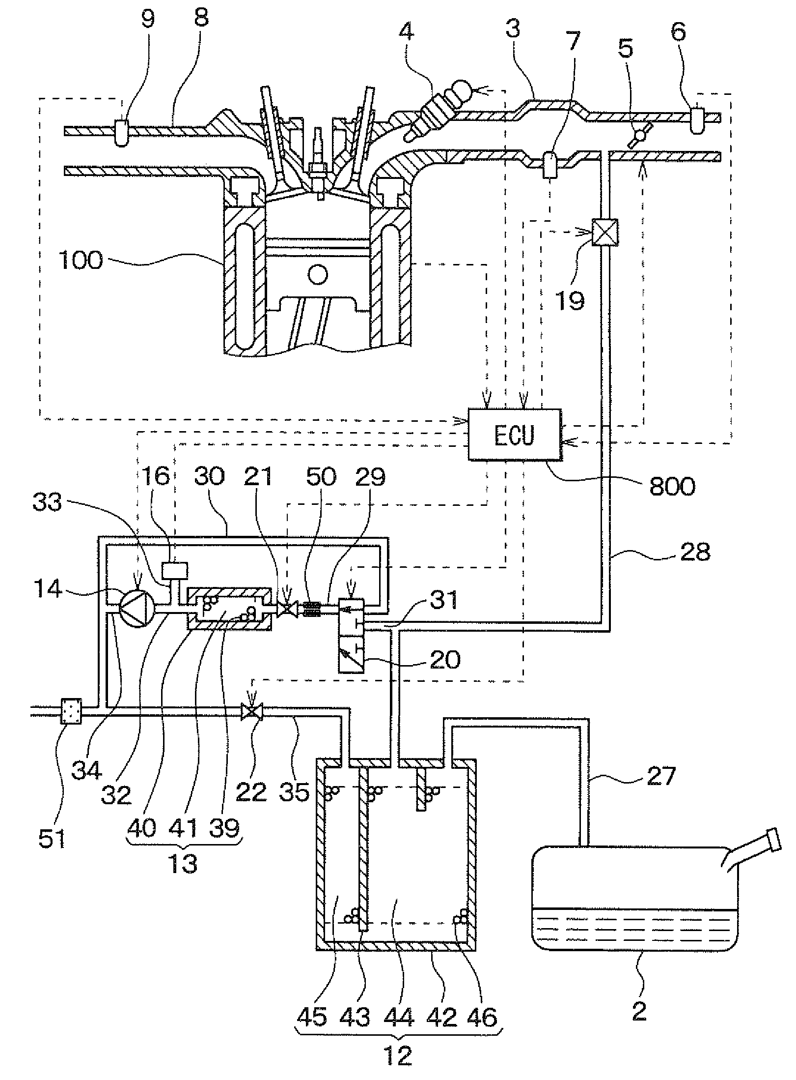
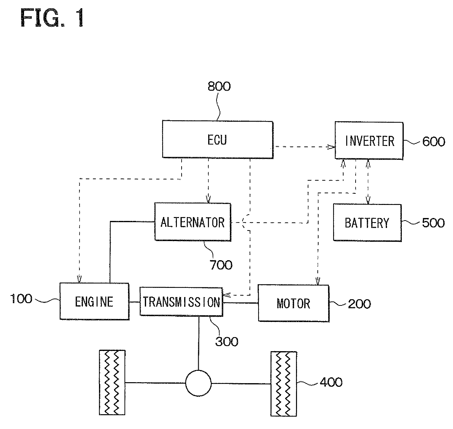
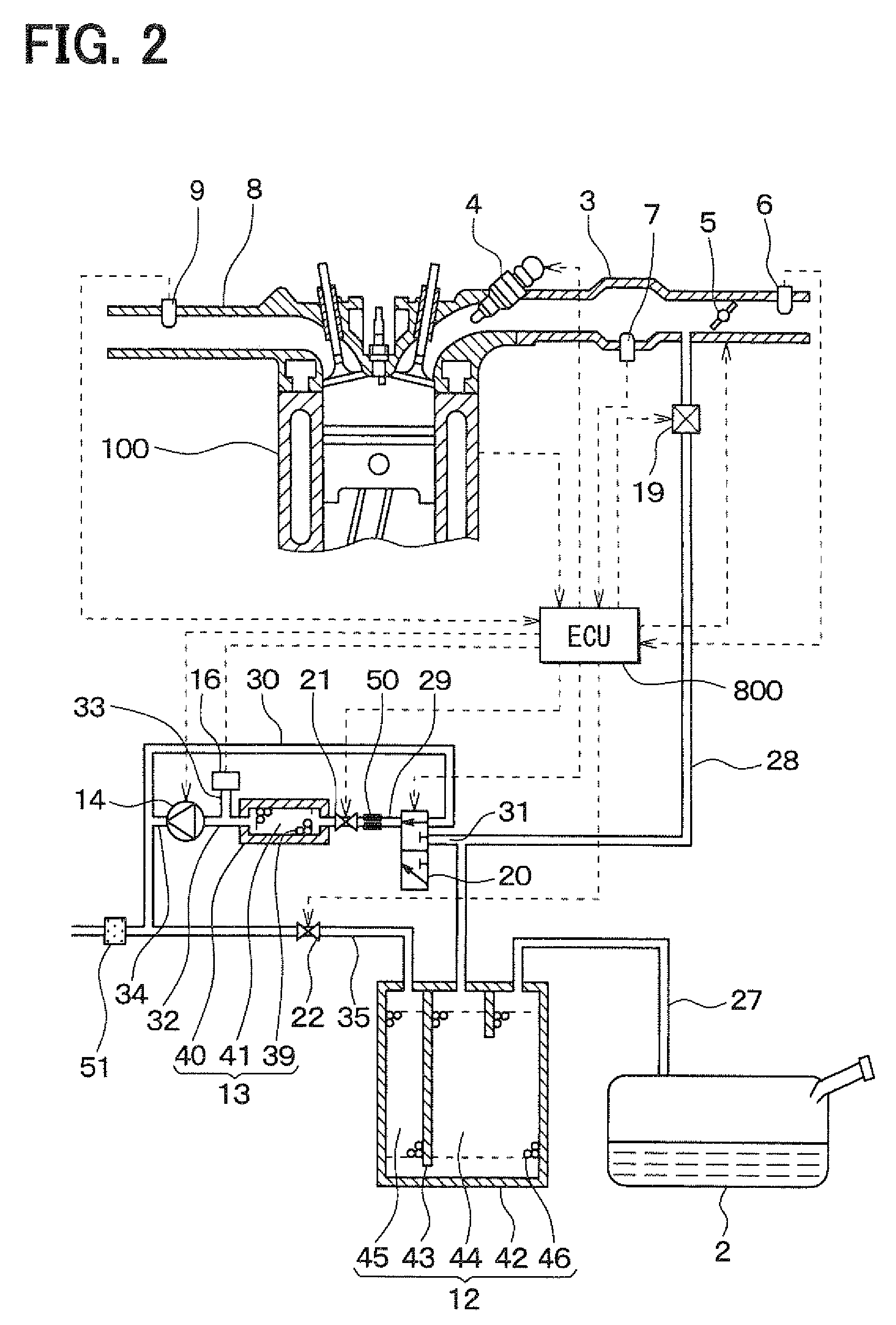
[0039]Hereafter, an embodiment of the present invention is described. FIG. 1 is a schematic view of the hybrid vehicle on which a fuel vapor treatment system of the present invention is mounted.

[0040]As shown in FIG. 1, the hybrid vehicle is provided with an internal combustion engine 100 and an electric motor 200 for driving the vehicle. The driving force is transmitted to drive wheels 400 through a transmission 300. The electric motor 200 receives electricity from a secondary battery 500 through an inverter 600. The inverter 600 converts direct-current voltage into alternating-current voltage and varies frequency of the alternating-current voltage so that the rotational speed of the motor 200 is controlled.

[0041]An alternator 700 driven by the engine 100 generates electricity when the amount of charge of the battery 500 is lowered than a specified value. The electricity generated by the alternator 700 is supplied to the battery 500 through the inverter 600 so that the battery is c...


PUM


Abstract

A fuel vapor treatment system is mounted on a hybrid vehicle having an internal combustion engine and an electric motor. Even when an internal combustion engine is stopped, a discharge of fuel vapor from a first canister to atmosphere can be detected. When the discharge of the fuel vapor from the first canister is detected, the internal combustion engine is started to perform a purge process. When it is detected that the purge process in the first canister is finished, the internal combustion engine is stopped to terminate the purge process.

Description

CROSS-REFERENCE TO RELATED APPLICATION[0001]This application is based on Japanese Patent Application No. 2007-303067 filed on Nov. 22, 2007, the disclosure of which is incorporated herein by reference.FIELD OF THE INVENTION[0002]The present invention relates to a fuel vapor treatment system for a hybrid vehicle which has an internal combustion engine and an electric motor for running.BACKGROUND OF THE INVENTION[0003]Conventionally, JP-5-18326A and JP-6-101534A show a fuel vapor treatment system in which fuel vapor generated in a fuel tank is temporarily adsorbed by a canister and a desorbed fuel vapor is purged into an intake passage of an internal combustion engine with air.[0004]Recently, a plug-in hybrid vehicle has been developed. In the plug-in hybrid vehicle, a battery is charged by an external power source while the vehicle is being parked, and the vehicle is driven by almost the electric motor.[0005]In a case that the plug-in hybrid vehicle is driven by only the electric mot...

Claims


Application Information

Patent Timeline
Patent Type & Authority Patents(United States)
IPC IPC(8): F02M33/02
CPCB60K6/48F02D41/0032F02M25/0818F02M25/0827F02M25/0836F02M25/089B60W20/00F02D41/187Y02T10/6221Y02T10/6269Y02T10/62B60K2006/268B60W10/06B60W20/15B60W2510/0614
Inventor AMANO, NORIYASUKOBAYASHI, MITSUYUKI
Owner DENSO CORP
Why Eureka
Try Eureka