Reflective screen

a technology of reflector light and screen, which is applied in the field of reflector light, can solve the problems of deviating the reflected color of projector light, limiting the diffusion angle and screen size, and not yet achieving the fundamental solution, and achieves the effects of low cost, high contrast, and easy formation

Inactive Publication Date: 2010-01-19
SONY CORP
View PDF12 Cites 9 Cited by
  • Summary
  • Abstract
  • Description
  • Claims
  • Application Information

AI Technical Summary

Benefits of technology

[0039]In the reflective screen according to any one of the above embodiments of the invention, the effect of diffusing external light from a ceiling to an observer is decreased to permit the display of an image with a high contrast, and thus the displayed image may be seen as a clear image even in a bright room illuminated with a fluorescent lamp or the like. Therefore, the reflective screen is useful as a screen for projectors such as a motion picture projector. Also, the reflective screen may be easily formed as a large reflective screen at low cost. Furthermore, a shift of white balance in the light diffusing layer is corrected by the light absorbing layer or the light reflecting layer, thereby permitting the display of an image with little shift of white balance.
[0040]When the reflective screen according to any one of the embodiments of the invention is used for a general take-up reflective screen, there occurs the problem of producing indentations in the reflective screen. However, in the take-up reflective screen according to any one of the above embodiments of the invention, the occurrence of indentations in the reflective screen is suppressed to decrease a difference in luminance due to the indentations. As a result, flatness and smoothness may be easily secured in the reflective screen, thereby preventing a decrease in quality of a projected picture.

Problems solved by technology

However, all the above-mentioned screens have complicated structures, and thus fundamental solution has not yet been achieved.
Japanese Unexamined Patent Application Publication No. 10-282577 discloses that a light diffusing layer is disposed as a surface layer, but has the problem of deviating the reflected color of projector light due to the light diffusing layer in which the reflection spectrum decreases toward the shorter wavelength side, as compared with general screens.
In addition, Japanese Patent Nos. 3655972, 2976148, and 2984801 each use a Fresnel lens and thus have limitations to the diffusion angle and the screen size due to the shape of the Fresnel lens.

Method used


Image

  • Reflective screen
  • Reflective screen
  • Reflective screen

Examples


example 1

[0210]Examples of the invention will be described.

(1) Reflective Screen Sample

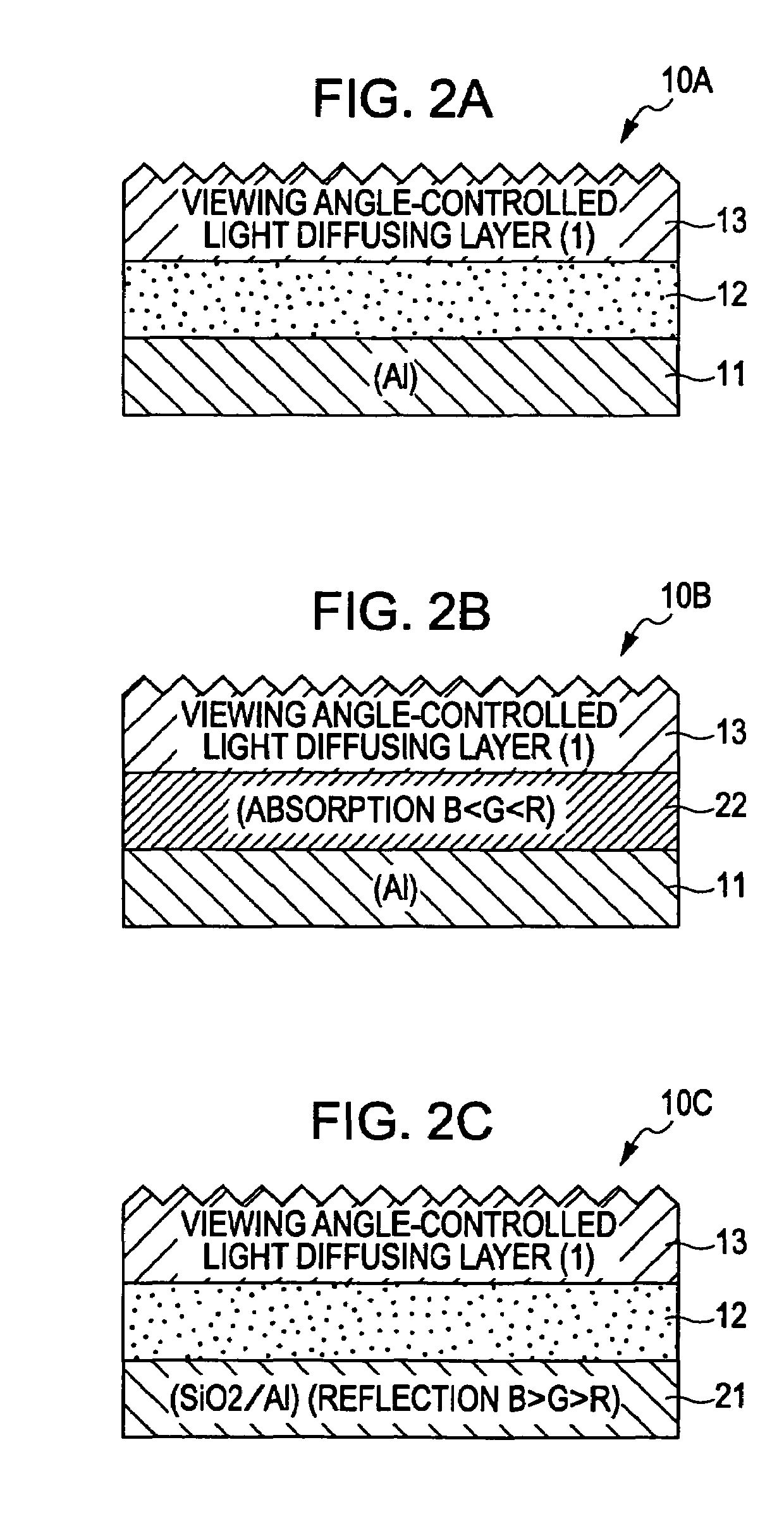
[0211]The reflective screen 10B according to the embodiment of the invention was formed according to the following procedures:

[0212](S11) Al was deposited to a thickness of 50 nm on a PET film (thickness 100 μm) by sputtering to form the light reflecting layer 11.

[0213](S12) The PET film (thickness 100 μm) was uniformly coated with an ultraviolet curable resin, and a mold having irregularity formed by sand blasting was pressed on the resin coating layer. Then, the resin coating layer was cured by ultraviolet irradiation, and the mold was removed to form, on the PET film, a resin film with the irregularity transferred thereon. The resin layer was used as the light diffusing layer 13. The light diffusing layer 13 exhibited the diffusion properties shown in FIG. 3. In other words, the diffusion angles in the A-axis direction and in the B-axis direction were 21° and 36°, respectively, and the half-luminance in...

example 2

[0217]A reflective screen was formed by the same method as in Example 1 except that an acrylic transparent adhesive tape (TD06A manufactured by Tomoegawa Paper Co., Ltd.) was used instead of the light absorbing layer 12.

example 3

[0218]The reflective screen 30C according to one of the embodiments of the invention was formed according to the following procedures:

[0219](S21) A PET film (thickness 100 μm) was uniformly coated with an ultraviolet curable resin, and a mold having irregularity formed by sand blasting was pressed on the resin coating layer. Then, the resin coating layer was cured by ultraviolet irradiation, and the mold was removed to form, on the PET film, a resin film with the irregularity transferred thereon. The resin layer was used as the light diffusing layer 13. The diffusion properties of the light diffusing layer 13 are shown in FIG. 19. In other words, the diffusion angles in the A-axis direction and in the B-axis direction were 36° and 50°, respectively, and the half-luminance incidence angles on one (positive incidence angle side) of the sides and the other side (negative incidence angle side) on the A axis were 20° and 16°, respectively. On the other hand, the half-luminance incidence ...


PUM


Abstract

A reflective screen includes a light reflecting layer, and a light diffusing layer provided on the light reflecting layer. The light diffusing layer has the diffusion property that in one (A axis) of two perpendicular axial directions on a light diffusion plane, a luminance distribution curve versus incidence angle is asymmetric with respect to the zero-incidence-angle axis, and the side on which the incidence angle (half-luminance incidence angle) with half of a peak luminance on the A axis in the normal direction to the screen plane is small faces in a direction in which external light has the highest strength.

Description

CROSS REFERENCES TO RELATED APPLICATIONS[0001]The present invention contains subject matter related to Japanese Patent Application JP 2005-188247 filed in the Japanese Patent Office on Jun. 28, 2005 and Japanese Patent Application JP 2006-168654 filed in the Japanese Patent Office on Jun. 19, 2006, the entire contents of which are incorporated herein by reference.BACKGROUND OF THE INVENTION[0002]1. Field of the Invention[0003]The present invention relates to a reflective screen.[0004]2. Description of the Related Art[0005]Reflective screens having the reflection property of reflecting light from projectors and the diffusion property of diffusing reflected light are used as screens for projectors such as OHP (Over Head Projectors), slides, motion picture projectors, and the like. The most general screen includes a laminate of a black backing sheet and a white poly(vinyl chloride) sheet used as a light reflecting base material. There have also been used reflective screens each includi...

Claims


Application Information

Patent Timeline
Patent Type & Authority Patents(United States)
IPC IPC(8): G03B21/56G02B5/02G03B21/60
CPCG03B21/602
Inventor SHIMODA, KAZUHITOKAJIYA, SHUNICHIWATANABE, TAKASHIKAKINUMA, MASAYASUKISO, HIROYUKICHUBACHI, HIDEYAHAYASHI, HIROSHIHOSOYA, KENMURAKAMI, AKIKOISHIKAWA, KOKONDO, SHINICHI
Owner SONY CORP
Why Eureka
Try Eureka