
Method and apparatus for determining neighboring routing elements and rerouting traffic in a computer network

a computer network and routing element technology, applied in the field of network communication system maintenance, can solve the problems of ospf routing protocol suffer, prone to errors in the rerouting procedure, disabled links and are no longer viable, etc., and achieve the effect of facilitating tasks

Inactive Publication Date: 2010-01-19
AMERICAN TELEPHONE & TELEGRAPH CO
View PDF17 Cites 25 Cited by
  • Summary
  • Abstract
  • Description
  • Claims
  • Application Information

AI Technical Summary

Benefits of technology

[0026]Accordingly, it is an object of the present invention to provide a operator definable interface, which facilitates the tasks required to gracefully cost out a routing element in a computer network before conducting maintenance on that routing element and reverse the process following maintenance, whether these tasks are performed automatically or manually, without a priori knowledge of network topology.
[0027]It is another object of the present invention to reduce or eliminate human error, such as incorrect cost changes, skipped interfaces, and asymmetric cost changes, before and after maintenance due to reconfiguration of routing elements in a computer network.
[0028]It is yet another object of the present invention to significantly decrease operator activity during the maintenance of a routing element in a computer network.
[0029]It is still another object of the present invention to provide substantial improvements in maintenance procedures and performance due to a decrease in packet loss across a computer network.
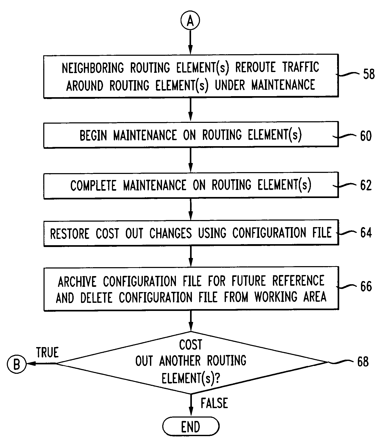
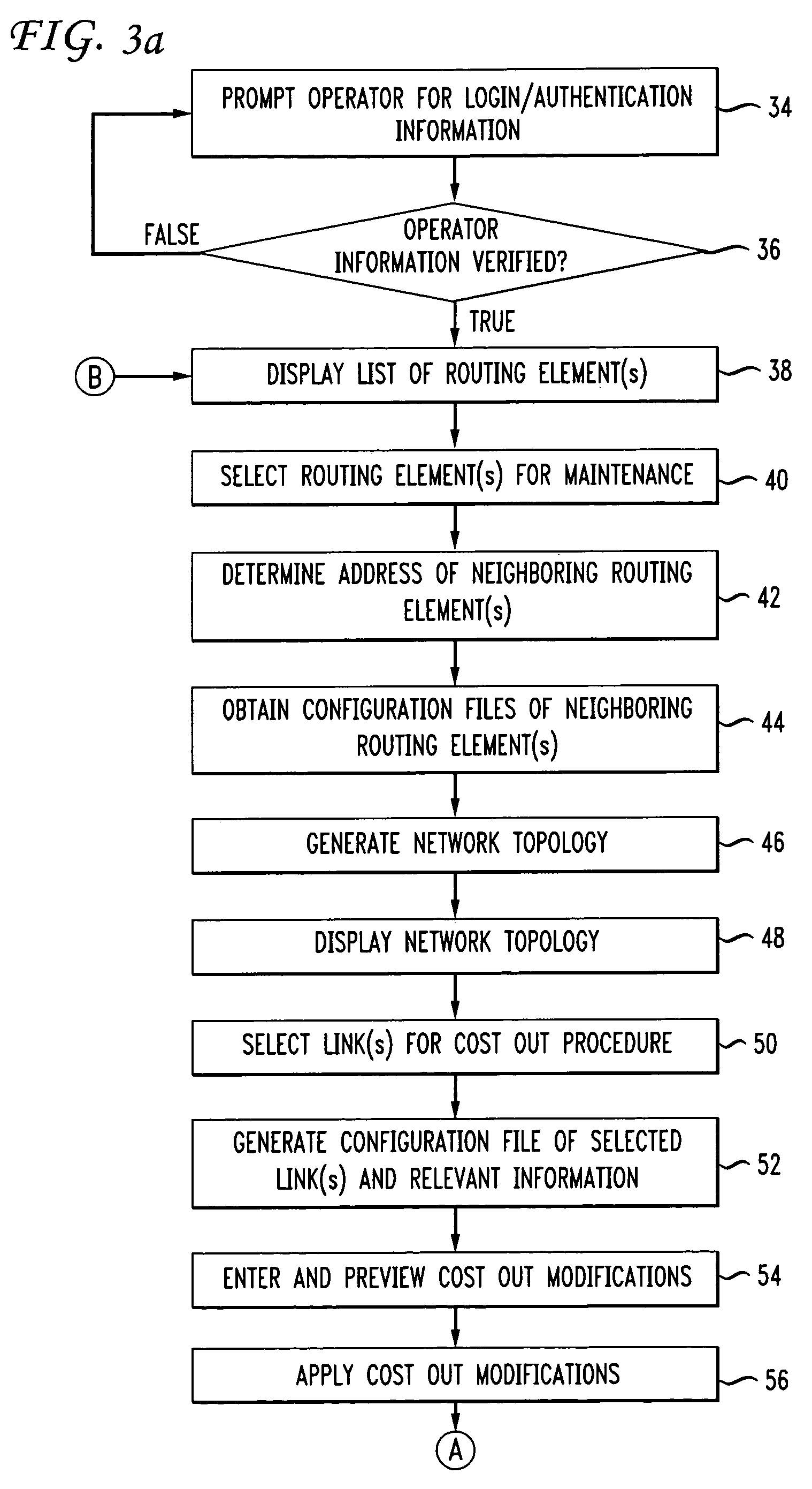
[0033]Embodiments of the present invention relate to a method of routing network traffic around a routing element in a computer network. The method includes the steps of selecting a routing element, applying a subnet mask to an interface address associated with the selected routing element to generate a plurality of subnet addresses, determining an address of a neighboring routing element linked to the selected routing element from the subnet addresses, and obtaining configuration information from the neighboring routing element. The method also includes determining a network topology from the configuration information, selecting one of a plurality of links in the network topology, and modifying a cost associated with the selected link. The modified cost is adapted to render the selected link less desirable for routing therethrough, thereby routing network traffic around the selected routing element.

Problems solved by technology

Such maintenance may be implemented by a network system administrator, but it tedious and prone to errors in the rerouting procedure.
In addition, the OSPF protocol may determine alternative routes for current routes that utilize disabled links and are no longer viable when a particular network node is removed from active service due to periodic or non-routine maintenance.
However, the OSPF routing protocol suffers from several disadvantages.
In particular, this protocol takes a finite time interval to detect and repair a broken or disabled route.
Although this is unavoidable in cases where the route becomes disabled due to an unforeseen event, protocol efficiency is less than optimal when a priori knowledge is available concerning network topology changes that affect viability of routes, for example, when a network node is scheduled for maintenance or upgrading.
Data networks, such as those maintained by communication service providers that perform any type of regular maintenance or upgrades on routable networks experience loss and delay of data packets due to routing re-convergence during maintenance.
In addition, complex non-automated configuration changes are prone to human error.
In many instances, this manual procedure leads to incorrect or missed link cost configurations, and asymmetric cost restorations, which result in Plant Operator Error (POE) and an increase in Defects per Million (DPM).

Method used


Image

  • Method and apparatus for determining neighboring routing elements and rerouting traffic in a computer network
  • Method and apparatus for determining neighboring routing elements and rerouting traffic in a computer network
  • Method and apparatus for determining neighboring routing elements and rerouting traffic in a computer network

Examples


Embodiment Construction

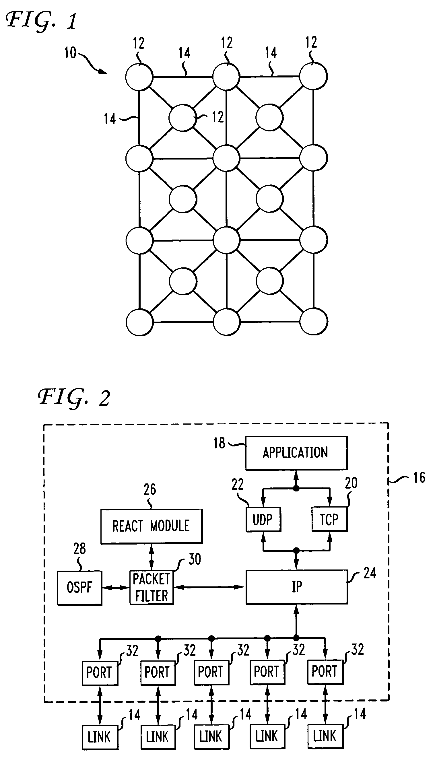
[0051]The present invention essentially overcomes problems in the prior art by enabling operations engineers to select a routing element, automatically query the chosen element for its current Open Shortest Path First (OSPF) or other routing protocol settings, and enable one or more OSPF settings to be changed so that the selected routing element can be gracefully cost out. A cost is associated with the output side of each router interface or link. This cost is configurable by a system administrator. The lower the cost, the more likely the interface is to be used to forward data traffic. “Cost out” refers to the adjustment of the cost associated with links leading to a routing element such that these paths will gradually be circumvented by other routing elements, thereby diverting traffic away from the routing element to be “cost out”. Current settings are preferably recorded for automatic restoration following the completion of maintenance.

[0052]Recent and evolving Internet Protoco...


PUM


Abstract

A method and apparatus for rerouting traffic in a computer network select a routing element, apply a subnet mask to an interface address of the routing element to generate subnet addresses, determine the address of neighboring elements from the subnet addresses, and obtain configuration information from the neighboring elements. Network topology is determined from the configuration information, a link in the network topology is selected, and a cost associated with the link is modified. The modified cost renders the link less desirable for routing. A method and apparatus for determining the address of neighboring routing elements in a computer network, combine a subnet mask and interface address associated in a bitwise AND operation to generate subnet addresses, disregard the highest and lowest subnet addresses and the address of the selected routing element from the subnet addresses, and identify the remaining subnet address as associated with the neighboring routing element.

Description

TECHNICAL FIELD[0001]The present invention relates generally to network communication system maintenance, and more particularly to an automated method of rerouting network traffic away from a particular routing element undergoing maintenance.BACKGROUND OF THE INVENTION[0002]Rerouting is important where a particular network router is in need of routine or immediate maintenance. Such maintenance may be implemented by a network system administrator, but it tedious and prone to errors in the rerouting procedure. Dynamic routing in an Internet Protocol (IP)-based communication network is typically accomplished by employing an Interior Gateway Protocol (IGP), such as an Open Shortest Path First (OSPF) routing protocol. The OSPF protocol is essentially an internetworking or gateway protocol that facilitates communications with external networks.[0003]Routing is accomplished in the OSPF protocol by each network node having a routing database containing information related to network topolog...

Claims


Application Information

Patent Timeline
Patent Type & Authority Patents(United States)
IPC IPC(8): G01R31/08
CPCH04L41/12H04L45/02H04L45/123H04L45/22H04L45/28
Inventor BADAT, QASSIM AYUBROSEMAN, ADAM CRAIG
Owner AMERICAN TELEPHONE & TELEGRAPH CO
Learn More