Methods and apparatus for managing a user interface on a powered network

a user interface and powered network technology, applied in the direction of liquid/fluent solid measurement, data switching details, instruments, etc., can solve the problems of complex and difficult management of personal computers, complicated installation, and associated installation and ongoing maintenance costs, and achieve the effect of efficient operation

a user interface and powered network technology, applied in the direction of liquid/fluent solid measurement, data switching details, instruments, etc., can solve the problems of complex and difficult management of personal computers, complicated installation, and associated installation and ongoing maintenance costs, and achieve the effect of efficient operation

US7650519B1Active Publication Date: 2010-01-19TERADICI CORP

Image

  • Methods and apparatus for managing a user interface on a powered network
  • Methods and apparatus for managing a user interface on a powered network
  • Methods and apparatus for managing a user interface on a powered network

Examples


case 520

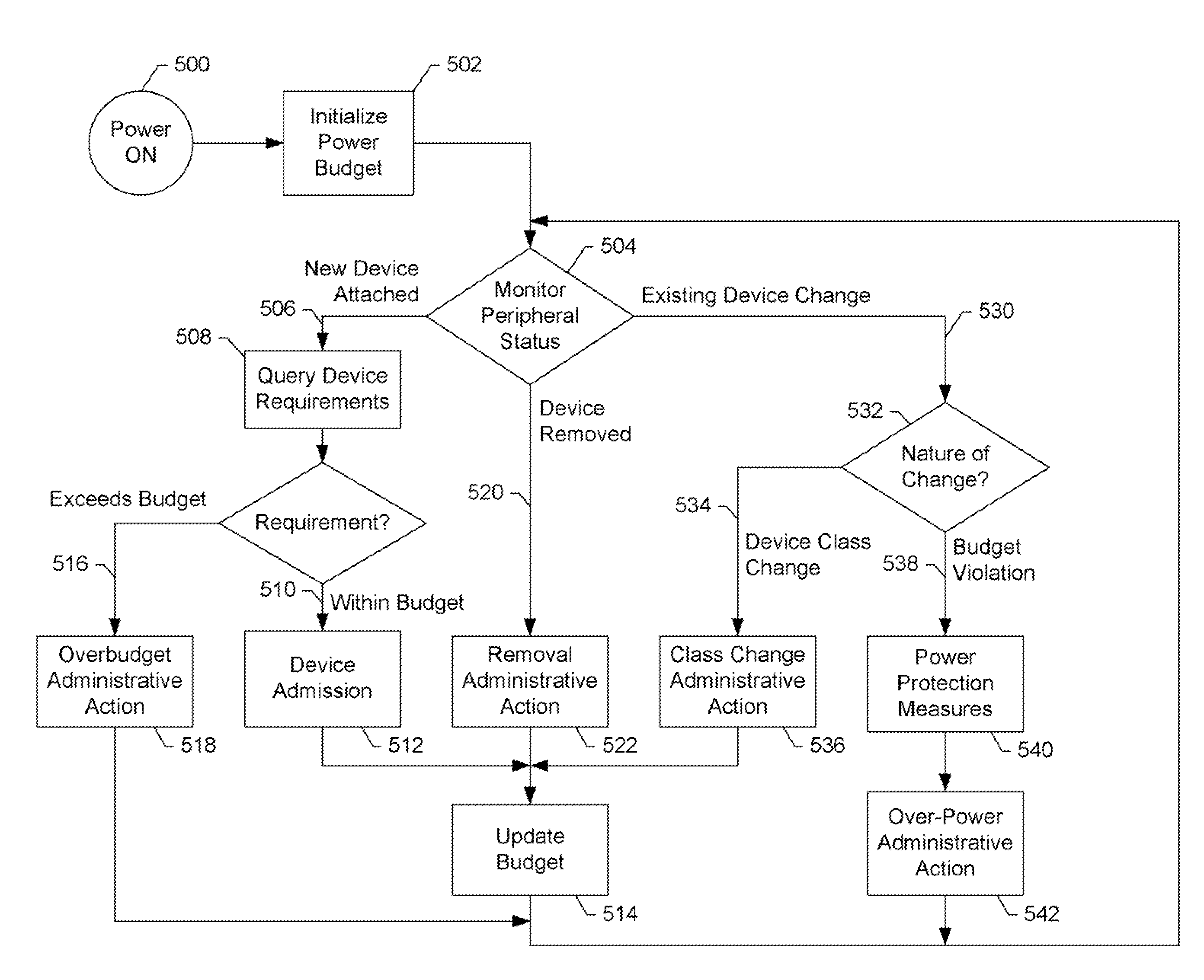
[0044]In case 520, a device is removed so removal administrative action is optionally taken as step 522 and the current power budget is updated as step 514. For example, when the device is removed, a host administration function may be notified. The system then returns to step 504.

[0045]In case 530, the power characteristics or consumption of a device changes so step 532 tests the action to be taken dependant on the nature of the change. In one embodiment, a change in power consumption related to one peripheral device has the effect of changing the class of another peripheral device. For example, a mouse changing from a standby mode in which minimal power is consumed to an operational mode in which a nominal power is consumed may trigger an automatic change in power class for an associated display monitor peripheral from a standby power consumption to nominal operating power consumption. In another embodiment, the change is associated with the same device. In case 534 there is a det...


PUM


Abstract

A system and methods for connecting a graphic user interface to a powered network is disclosed. The network-powered graphic user interface system converts encoded computer user interface signals transmitted over a powered network cable to multiple signal sets, each set associated with a peripheral device interface. Methods for managing the admission of the peripheral devices are also described. Connection criteria include the power budget for the connection, device characteristics, device power requirements and the characteristics of other devices sharing the powered network connection.

Description

RELATED APPLICATIONS[0001]This application claims priority to U.S. Provisional Patent Application Ser. No. 60 / 726,485, entitled REMOTE GRAPHIC USER INTERFACE SYSTEM AND METHODS USING POWER OVER ETHERNET, filed Oct. 12, 2005, incorporated herein by reference in its entirety.FIELD OF THE INVENTION[0002]The present invention relates broadly to providing an interface between a host computing appliance and a user interface. Specifically, the present invention relates to managing a remote graphic user interface including display and peripheral devices over a powered network connection.BACKGROUND OF THE INVENTION[0003]Historic advances in computer technology have made it economical for individual users to have their own computing system which caused the proliferation of the Personal Computer (PC). Continued advances of this computer technology have made these personal computers very powerful but also complex and difficult to manage. To improve manageability in workplace environments, it ha...

Claims


Application Information

Patent Timeline
19 Jan 2010
Publication
US7650519B1
IPC
G06F1/00; G06F1/32
CPC
G06F1/266; G06F3/023; G06F3/038; H04L12/10
Inventors
HOBBS, DAVID VICTOR; MAIN, IAN CAMERON