Endoscopic image pickup method and magnetic resonance imaging device using the same

a pickup method and magnetic resonance imaging technology, applied in the field of endoscopic image pickup method and magnetic resonance imaging device using the same, can solve the problems of inability to apply the method to the iv-mri, difficult to confirm the insertion position of the catheter, disadvantages of conventional mri apparatus, etc., to achieve short measuring time, reduce the number of slices, and reduce the time of three-dimensional image data

Inactive Publication Date: 2010-01-26
HITACHI MEDICAL CORP
View PDF25 Cites 56 Cited by
  • Summary
  • Abstract
  • Description
  • Claims
  • Application Information

AI Technical Summary

Benefits of technology

[0010]According to the above-mentioned imaging method, the three-dimensional image data can be obtained by sliding a body cavity to a plurality of portions in a lengthwise direction as well as the tip position and the direction of the catheter can be detected based on the three-dimensional image data. As a result, an image, which uses the tip of the catheter as a view point and is similar to an image taken by an endoscope (cruising view), can be reconstructed by a known center projected method. Accordingly, an operator can insert the catheter while observing the state of the inside wall of the body cavity, which is observed from the tip of the catheter, in real time, and this is effective to the insertion of the catheter in IV-MRI. For example, when a blood vessel is branched at a forward position, the operator can determine the branch of the blood vessel, to which a catheter is desired to guide, while observing it from a side. In particular, when the guide wire, which was blindly inserted first, is inserted into a different branch, it is easy to draw out the guide wire a little and to insert it again.
[0012]In response thereto, another imaging method is provided in another aspect of this disclosure, wherein three-dimensional image data, which is reconstructed by executing an MR imaging sequence to a plurality of slices that intersect the guide wire, is stored. Then, the tip position and the inserting direction of the catheter can be detected by executing a measuring sequence, which measures the NMR signals of the tip of the catheter in the three-axis directions thereof, projecting the measured NMR signals in the respective axis directions and using the projections of the three axes to which the NMR (nuclear magnetic resonance) signals are projected. That is, when the tip position and the inserting direction of the catheter is detected by a three-axis projection method having a short measuring time, the real time imaging property can be maintained by increasing the frequency of detection of the tip position and the inserting direction of the catheter even if the imaging frequency of the three-dimensional image that takes a long measuring dine is reduced. That is, the imaging sequence of the three-dimensional image data, which is used as the base of the center projection, can be executed once every time the processing for rearranging a center projected image by detecting the tip position and the inserting direction of the catheter is executed once.
[0013]Further, in still another imaging method, according to another aspect of this disclosure, the number of slices can be reduced by detecting the tip position and the inserting direction of the catheter by executing beforehand the measuring sequence that measures the NMR signals of the tip of the catheter in the three-axis directions thereof, setting sliced positions forward of the detected tip position of the catheter, and executing the MR imaging sequence of a plurality of sliced images intersecting the guide wire, and thereby the measuring time of the three-dimensional image data can be reduced.
[0014]In the above-mentioned approaches, a ring-shaped marker, which is provided at the tip of the catheter coaxially with the catheter, can be used as the peculiar index. In this case, it is preferable to provide at least two markers at the tip of the catheter by displacing the positions thereof in the axial direction of the catheter. According to the above arrangement, an accuracy of detecting the direction of the catheter can be improved as compared with the case in which one marker is provided.

Problems solved by technology

Accordingly, the conventional MRI apparatuses are disadvantageous in an application for confirming the position of a catheter inserted into a body cavity such as a blood vessel having a curving portion because they cannot uniquely determine a sliced plane including the catheter.
Since, however, a sliced plane including the catheter having a curved portion cannot be uniquely determined, it is not always easy to confirm the inserted position of the catheter.
Accordingly, the method cannot be applied to the IV-MRI which executes imaging and display of an image in real time.
When the guide wire is composed of a receiving antenna and the intervals of the slices of the three-dimensional image data to be imaged are narrowed, an imaging time of the three-dimensional image data is increased, and thus there is a possibility that a real time imaging property may be deteriorated.
Accordingly, when the intervals of the slices of the three-dimensional image data is widened, it is contemplated that detecting peculiar indexes provided with the catheter based on the three-dimensional image data is difficult.

Method used


Image

  • Endoscopic image pickup method and magnetic resonance imaging device using the same
  • Endoscopic image pickup method and magnetic resonance imaging device using the same
  • Endoscopic image pickup method and magnetic resonance imaging device using the same

Examples


Embodiment Construction

[0029]Embodiments of the present invention will be explained with reference to the figures in detail.

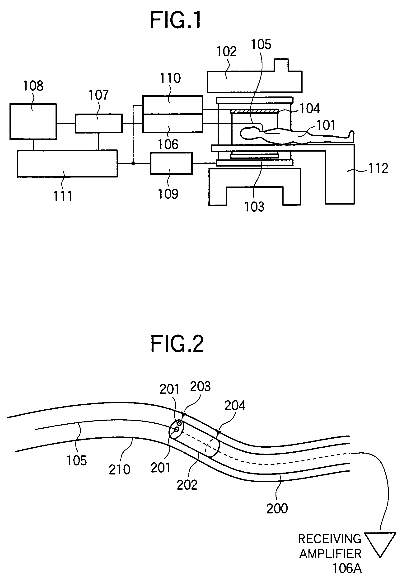
[0030]FIG. 1 shows the overall arrangement of an MRI apparatus to which the present invention is applied. The MRI apparatus includes a static magnetic field magnet 102, a gradient magnetic field generating coil 103, an RF irradiating coil 104, a guide wire 105 that also acts as an RF receiving antenna for detecting nuclear magnetic resonance signals generated from a patient 101, and a bed 112 for carrying the patient into a measuring space, and these components are installed in an imaging room. The static magnetic field magnet 102 generates a uniform magnetic field in the measuring space, the gradient magnetic field generating coil 103 gives a magnetic field gradient to the static magnetic field generated by the static magnetic field magnet 102, and the RF irradiating coil 104 irradiates a high frequency magnetic field to the patient placed in the measuring space.

[0031]A permanent ma...


PUM


Abstract

An endoscope-like image taking method includes providing at least one peculiar index, which can be discriminated from other portions on an MR image, at the tip of a catheter, previously inserting a metal guide wire for guiding the catheter into a body cavity of a patient inserting the catheter into the body cavity along the guide wire, executing an MR imaging sequence of a plurality of sliced images intersecting the guide wire, reconstructing three-dimensional image data based upon the nuclear magnetic resonance signals, which are received by the guide wire, and determining the tip position and the inserting direction of the catheter by detecting the peculiar index provided at the tip of the catheter based upon the three-dimensional image data, and reconstructing the center projected image using the three-dimensional image data and setting the tip position and the inserting direction of the catheter as a view point and a line-of-sight direction and displaying the center projected image on a display means.

Description

TECHNICAL FIELD[0001]The present invention relates to a magnetic resonance imaging apparatus (hereinafter, referred to as MRI apparatus), and more particularly, to a technology for taking and displaying an endoscope-like image of a body cavity such as a blood vessel and the like of a patient observed from a catheter inserted into the body cavity in real time.BACKGROUND ART[0002]An MRI apparatus is an apparatus for observing the inside of a patient by acquiring a tomogram and a frequency spectrum of a patient making use of a nuclear magnetic resonance phenomenon and includes a static magnetic field generator, a gradient magnetic field coil, a transmitting coil, and a receiving coil. The static magnetic field generator aligns the directions of the spins of nuclei (ordinarily, protons) that constitute the patient, the gradient magnetic field coil identifies the imaging slice of the patient as well as encodes position information to the nuclear magnetic resonance signals acquired from t...

Claims


Application Information

Patent Timeline
Patent Type & Authority Patents(United States)
IPC IPC(8): A61B5/05A61B5/055G01R33/34A61B19/00G01R33/32G01R33/36G06T1/00G06T5/00G06T7/00
CPCA61B5/06G01R33/286G06T5/006G06T7/73A61B34/20G06T2207/30004A61B90/361A61B2090/365A61B2090/3954A61B2090/3958A61B2090/374
Inventor YATSUO, TAKESHINAGAO, HISAKOSAKAKIBARA, KENJI
Owner HITACHI MEDICAL CORP
Why Eureka
Try Eureka