Check valve and pump including check valve
a check valve and pump technology, applied in the field of check valves, can solve the problems of inconvenience of replacing the o ring, the sealing property of the o ring can be degraded, etc., and achieve the effects of low cost, simple structure, and pressure applied
- Summary
- Abstract
- Description
- Claims
- Application Information
AI Technical Summary
Benefits of technology
Problems solved by technology
Method used
Image
Examples
first embodiment
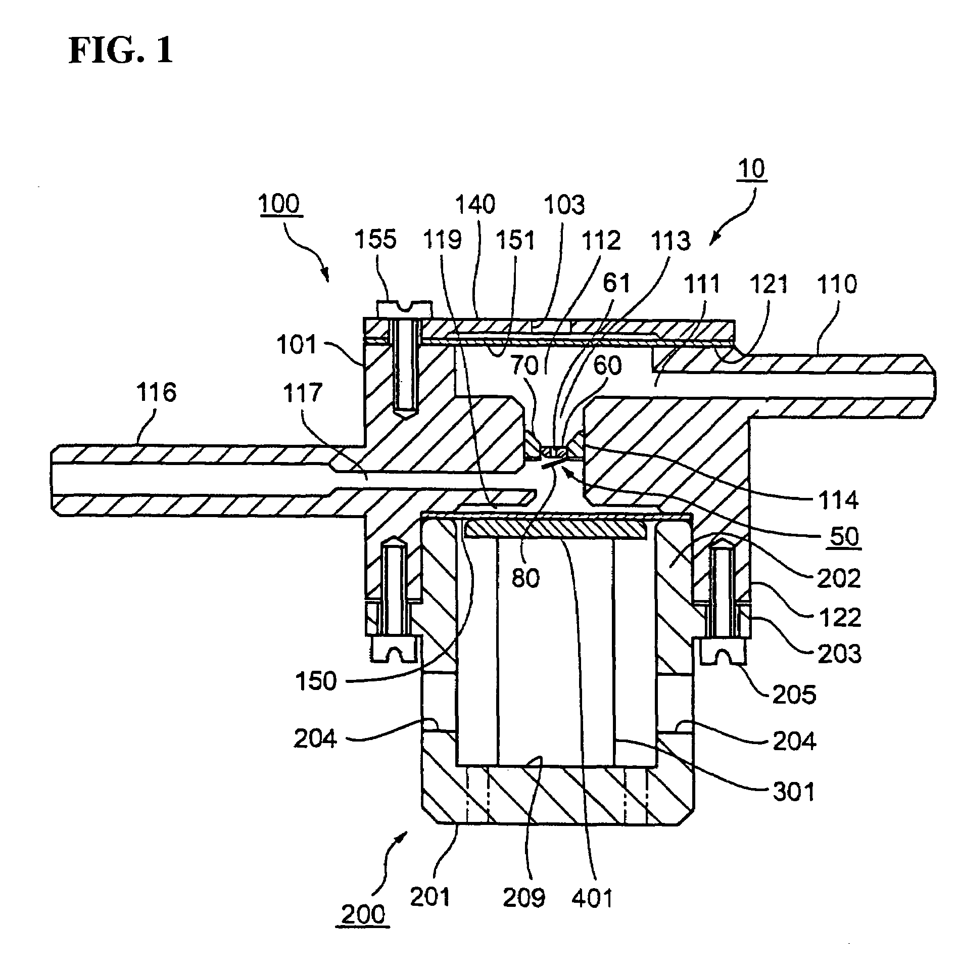
[0136]FIG. 1 is a longitudinal sectional view of the pump in which the check valve of the first embodiment is placed. In FIG. 1, the pump 10 includes a pump chamber unit 100 and an actuator unit 200.
[0137]The pump chamber unit 100 is made up of a pump chamber body 101 including an inlet flow pass 111 into which a working fluid is made to flow in and an outlet flow pass 117 from which the working fluid is made flow out, a diaphragm 150, and an elastic film 151 that may be used as pulsating flow absorption means for preventing a pulsating flow of the working fluid.
[0138]The pump chamber body 101 has an outside shape roughly like a cylinder in plan view. An inlet connection pipe 110 formed with the inlet flow pass 111 projects from one side of the pump chamber body 101, and the inlet flow pass 111 communicates with an elastic wall chamber 112. The tip of the inlet flow pass 111 is connected to external piping of a tube, etc., (not shown) for supplying the working fluid. On the opposite...
second embodiment
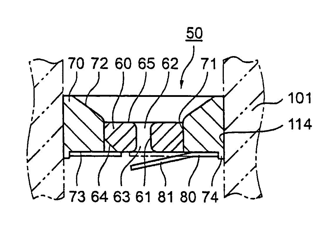
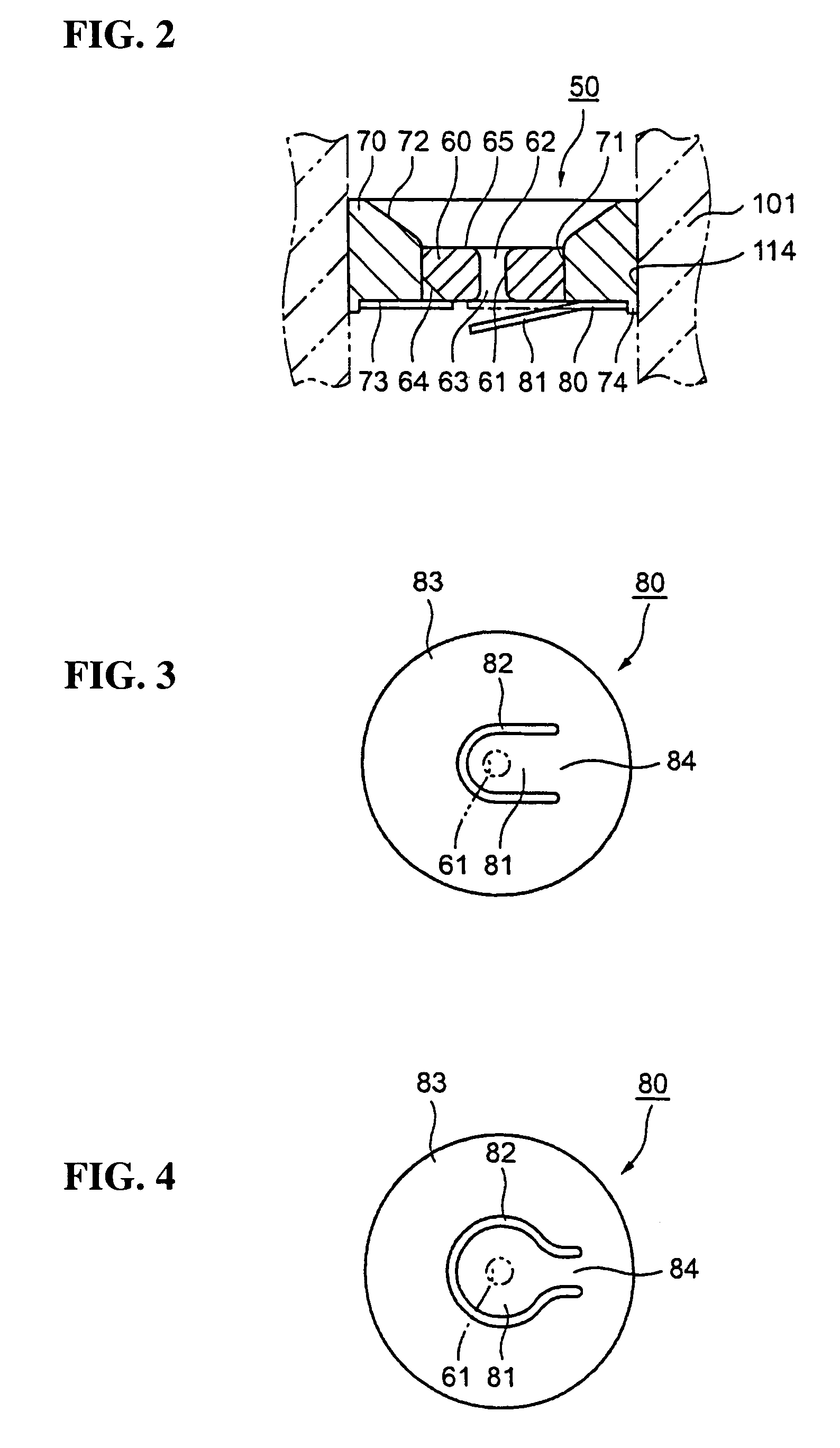
[0198]Therefore, in the second embodiment, the projection 74 of the valve seat frame 70 is crimped fully or partially, whereby the fixing part 83 of the valve body 80 is fixed to the valve seat frame 70. As such, the valve body 80 can be fixed in a small space reliably. The outer peripheral part of the fixing part 83 of the valve body 80 is fixed, whereby the valve body 80 can be fixed without deforming an opening-closing part 81 or a support part 84 (see FIG. 3) of the valve body 80.
[0199]The valve body 80 is simply placed in the projection 74 of the valve seat frame 70, whereby the position in the plane direction is regulated, so that the opening-closing part 81 can hermetically seal a communication hole 61 for the working fluid of the valve seat 60 reliably without using any special jig. FIG. 12 is a sectional view showing a check valve 50 of the third embodiment of the invention. In the third embodiment, the fixing structures of the valve bodies 80 to the valve seat frames 70 ar...
third embodiment
[0202]Therefore, in the third embodiment, the valve body 80 is fixed as the fixing part 83 provided on the periphery is sandwiched between the valve seat frame 70 and the fixing member 90 so that the valve body 80 can be fixed without producing an internal stress. Thus, the valve body 80 can be fixed without deforming the support part 84 or the opening-closing part 81.
PUM
 Abstract
Description
Claims
Application Information
 - R&D
- Intellectual Property
- Life Sciences
- Materials
- Tech Scout
- Unparalleled Data Quality
- Higher Quality Content
- 60% Fewer Hallucinations
Browse by: Latest US Patents, China's latest patents, Technical Efficacy Thesaurus, Application Domain, Technology Topic, Popular Technical Reports.
© 2025 PatSnap. All rights reserved.Legal|Privacy policy|Modern Slavery Act Transparency Statement|Sitemap|About US| Contact US: help@patsnap.com


