Clip machine

a clip machine and clip technology, applied in the field of clip machines, can solve the problems of packaging material damage and/or not being completely covered, unwound tools, failures, etc., and achieve the effects of less compression work, reduced risk of damage to packaging wrapping, and reduced wear and tear

Active Publication Date: 2010-02-02
POLY CLIP SYST
View PDF12 Cites 10 Cited by
  • Summary
  • Abstract
  • Description
  • Claims
  • Application Information

AI Technical Summary

Benefits of technology

[0011]Accordingly, the task of the present invention is to design the closure operation in a simple manner to make it more reliable process-wise.
[0014]In contrast, the level of the greatest expansion of the braid with the arrangement of the displacement elements or their movement direction as per the invention is cross-wise to the clip limbs of the open clip so that the risk of damage to the packaging wrapping is decreased. Furthermore, the use here of a clip with shorter limbs, in particular, to close a thin braid, would be beneficial, necessitating less compression work during the closing operation, and thus the wear and tear can be reduced.
[0015]Besides the advantages mentioned, the mechanism as per the invention has, furthermore, the advantage of reduced spatial dimensions of the elements engaging in the closing because of that same movement direction.
[0020]The second sealing tool, the die, can in fact also be fastened to a second (upper) closure lever mounted and driven by it so that it can pivot around the common pivotal axis of both closure levers. A linear back and forth movement of the die, however, improves the kinematics from the perspective of the uniform formation of the clip. This becomes noticeable during the use of different clip sizes, which, depending on the limb length of the unformed clip, causes the opening angle of the two pivotable closure levers to change at the moment of the contact of the die with the clip so that it does not engage simultaneously with both limbs. The result is that an undesired tilting or torsional moment occurs.

Problems solved by technology

In specific cases, namely, with relatively stiff packaging material, however, failures may occur, especially when the tubular braid formed by the displacement elements, acting together in pairs, and laid in the still open clamp fastener is pulled a little apart by the displacement elements in the area of the overlap.
During the subsequent closure of the clip around the tubular braid, there is a risk then of the packaging material being damaged and / or not being completely encompassed by the closed clip so that the closure is not tight.
A change of tools is not desired because of the potential risk of an incorrect manipulation.
However, what is involved here is a clip machine of another category where, in particular, an expansion movement of the displacement elements is not planned and technically is also not possible.
For that reason, no braid free-from-heating can be formed with such a clip machine, which excludes the processing of raw sausage products.
The result is that an undesired tilting or torsional moment occurs.

Method used


Image

  • Clip machine
  • Clip machine
  • Clip machine

Examples


Embodiment Construction

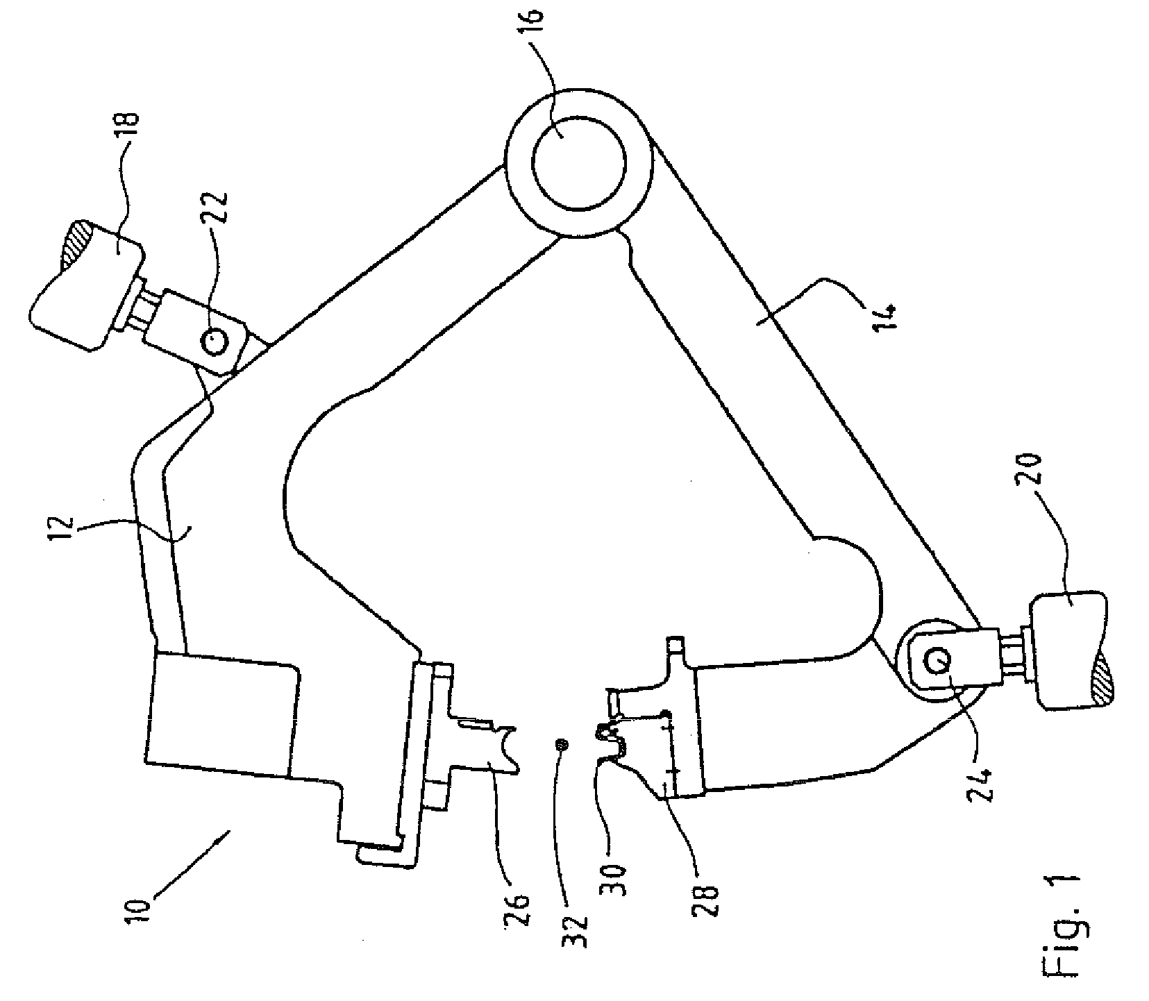
[0031]Closure system 10 of the sealing machine as per the invention has an upper, linearly conducted sealing slider 12 and a lower closure lever 14. The upper sealing slider 12 is driven by an actuator 18 whose force is initiated via articulation 22. The lower closure lever 14 is arranged pivotally around an axis 16. The pivotal movement of lower closure lever 14 is driven by a cam plate, not shown, and transferred via lifter rod 20, which engages with it at articulation 24 to closure lever 14. Die 26 is fastened to upper sealing slider 12 and die plate 28 to lower closure lever 14. An open clamp fastener 30 is held in die plate 28. Between die 26 and die plate 28 with open clamp fastener 30 there is an intestinal braid 32 to be closed, here represented in a simplified manner as a point.

[0032]To close the intestinal braid, die 26 and die plate 28 are moved towards one another through a pivotal movement of closure levers 12, 14 in such a manner that first die plate 28 is driven with ...


PUM


Abstract

A clip machine for dividing and sealing tubular-shaped packaging filled with stuffing having at least two axially spaced pairs of radially opposed displacement elements, relating to the axis of the packaging tube, which are linked to and equipped with a linear guide, to be compressed radially towards one another and then separated axially in pairs, for the local constriction of the filled packaging and the formation of a tubular braid radially-linearly, and a pivotably arranged first sealing tool and a second sealing tool, with the first and second sealing tools being equipped to set and close at least one clamp fastener around the formed tubular braid, to be compressed radially between the axially separated displacement element pairs, the radial movement direction of displacement element pairs coincides with the radial movement direction of sealing tools.

Description

BACKGROUND AND SUMMARY OF THE INVENTION[0001]The invention concerns a clip machine for the dividing and closing of tubular packaging (packaging tube) filled with a stuffing, with at least two axially spaced pairs of radially opposed displacement elements relating to the axis of the packaging tube (tube axis), which are linked and set up with a linear guide, to be compressed radially, linearly towards one another and subsequently in pairs separated axially (expanded) for the local constriction of the filled packaging and the formation of a tubular braid; with a first and then a second sealing tool, which tools are set up to set and close at least one clamp fastener (clip) around the tubing braid that had been formed between the axially separated displacement element pairs, compressed radially towards one another.[0002]Clip machines of this type are known, for example, from DE 196 44 074 C1 (U.S. Pat. No. 6,217,436). Such clip machines are used to close tubular packaging tubes, intest...

Claims


Application Information

Patent Timeline
Patent Type & Authority Patents(United States)
IPC IPC(8): A22C11/12
CPCA22C11/125
Inventor EBERT, DETLEFHUMMEL, MICHAEL
Owner POLY CLIP SYST
Why Eureka
Try Eureka