Triple gate and double gate finFETs with different vertical dimension fins

a technology of fins and fins, applied in the field of fins, can solve the problems of less device design area efficiency, unique design challenges of fins, and the use of longer channel lengths not only consumes more silicon substrate area, but achieves the effect of optimal sram design and easy tuning

Active Publication Date: 2010-02-02
GLOBALFOUNDRIES U S INC
View PDF4 Cites 74 Cited by
  • Summary
  • Abstract
  • Description
  • Claims
  • Application Information

AI Technical Summary

Benefits of technology

[0011]The present invention addresses the needs described above and provides structures and methods of forming finFET devices of multiple vertical dimensions for the fins with a small number of additional processing steps that are simple and inexpensive.
[0012]Furthermore, the present invention enables design of a dense high performance CMOS device by providing multiple vertical dimensions for the fins of finFET devices.
[0013]While more than two different vertical dimensions for the fins are enabled according to the present invention, the present invention is herein described with two types of semiconductor fins with different vertical dimensions for the fins. Application of the present invention to more than two types of semiconductor fins is straightforward and requires only additional masks and implantation processes.
[0020]As a specific example of an application of the present invention, two n-type finFETs wherein the first NFET with a first fin has a full vertical dimension for the first fin and a second NFET with a second fin has about 50% of the full vertical dimension for the second fin are formed such that the first fin and the second fin are adjoined end to end in an SRAM design. The first n-type finFET is used for a pull down NFET and the second n-type finFET is used as a pass gate NFET in an SRAM cell. The ratio of about 2 between the vertical dimensions of these two finFETS enables the design of the two finEFTs with the same gate length and the same fin width while maintaining a beta ratio of about 2. By adjusting the depth of the implant for the implant species and consequently the amount of removal of the semiconductor material from the second type semiconductor fins, the beta ratio can easily be tuned for optimal SRAM design.
[0021]Similar benefits of the present invention can readily be extended to other circuits that can utilize different amount of on-current for different finFET devices.

Problems solved by technology

While providing improved MOSFET performance, the finFETs, however, pose unique design challenges.
Also, the use of multiple fins tends to use more silicon surface area and makes the device design less area-efficient.
However, transistors with different on-currents are often required in the design of high performance integrated circuits.
23-26, the use of longer channel lengths not only consumes more silicon substrate area, but also introduces variables in terms of the variability of the physical dimensions of the gate lengths due to the complexities of optical proximity correction.
In addition, different gate lengths give different short channel effect, which can cause threshold voltage mismatching or ratio variation induced by Vdd variation.
The oxidation raises surface level due to volume expansion caused by the oxidation, which causes vertical variation in the height of the substrate which reduces usable depth of focus during subsequent lithographic process and may cause CD variations in the printed lithographic images.

Method used


Image

  • Triple gate and double gate finFETs with different vertical dimension fins
  • Triple gate and double gate finFETs with different vertical dimension fins
  • Triple gate and double gate finFETs with different vertical dimension fins

Examples


Embodiment Construction

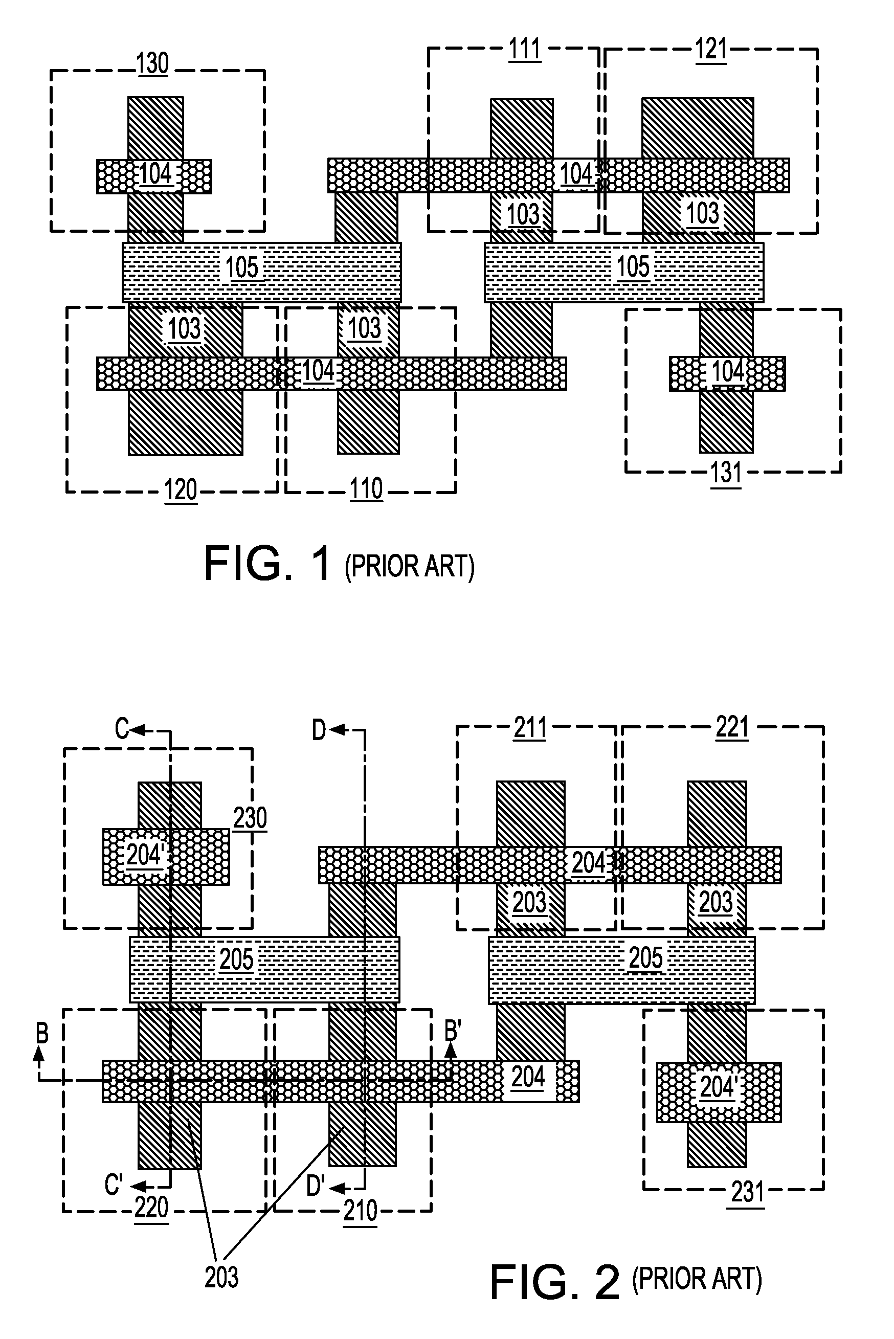
[0036]Before describing the present invention in detail, a discussion on the prior SRAM structures is provided. The discussion on the prior SRAM structures is made herein to clearly illustrate the advantages provided by the present invention over the prior art.

[0037]Referring to FIG. 1, a top-down schematic view of an exemplary six-transistor SRAM structure utilizing planar MOSFETs according to the prior art is shown. Located within the substrate (not shown explicitly) are semiconductor surfaces 103, gate electrodes 104, and a first level of metal wiring 105. These six transistors in the SRAM structure include a first pull up PFET 110, a first pull down NFET 120, a first pass gate NFET 130, a second pull up PFET 111, a second pull down NFET 121, and a second pass gate NFET 131. Noteworthy are the different widths between the semiconductor area for the first pull down NFET 120 and the corresponding semiconductor area for a first pass gate NFET 130 needed to maintain a beta ratio arou...


PUM


Abstract

A semiconductor structure and its method of fabrication include multiple finFETs with different vertical dimensions for the semiconductor fins. An implant species is implanted in a bottom portion of selected semiconductor fins on which reduced vertical dimension is desired. The bottom portion of the selected semiconductor fins with implant species is etched selective to the semiconductor material without the implanted species, i.e., the semiconductor material in the top portion of the semiconductor fin and other semiconductor fins without the implanted species. FinFETs with the full vertical dimension fins and a high on-current and finFETs with reduced vertical dimension fins with a low on-current thus results on the same semiconductor substrate. By adjusting the depth of the implant species, the vertical dimension of the semiconductor fins may be adjusted in selected finFETs.

Description

FIELD OF THE INVENTION[0001]The present invention relates to semiconductor devices, and particularly, to finFET devices.BACKGROUND OF THE INVENTION[0002]A FinFET transistor is a MOSFET transistor in which a gate electrode is placed on two, three, or four sides of a channel or is wrapped around the channel, with a gate dielectric separating the gate electrode and the channel. A double gate finFET utilizes a double gate configuration in which the gate electrode is placed on two opposite sides of the channel. In a triple gate finFET, the gate electrode is placed on one more side of a typically rectangular channel of the transistor. In a quadruple gate finFET or a wrapped gate finFET, the gate electrode is placed on four sides of the channel. The increased number of sides on which the gate electrode controls the channel of the finFET enhances the controllability of the channel in a finFET compared to a planar MOSFET. The improved control of the channel allows smaller device dimensions w...

Claims


Application Information

Patent Timeline
Patent Type & Authority Patents(United States)
IPC IPC(8): H01L29/72
CPCH01L21/845H01L27/1211H01L29/66795H01L29/785
Inventor ZHU, HUILONGTAN, YUE
Owner GLOBALFOUNDRIES U S INC
Why Eureka
Try Eureka