Direct determination of rigid body motion using data collected from independent accelerometers

Active Publication Date: 2010-02-02
ANSYS
View PDF5 Cites 9 Cited by
  • Summary
  • Abstract
  • Description
  • Claims
  • Application Information

AI Technical Summary

Benefits of technology

[0009]One of the objects, features, and advantages of the present invention is to consistently create a set of numerical rigid body motion data for a computer simulation directly from data collected from accelerometers with minimized measurement errors and repeatable determination.

Problems solved by technology

However, converting such measured data is not straight forward and has a number of problems including, but not necessarily limited to, 1) reducing redundant data, 2) minimizing measurement error, and 3) producing consistent determination.

Method used


Image

  • Direct determination of rigid body motion using data collected from independent accelerometers
  • Direct determination of rigid body motion using data collected from independent accelerometers
  • Direct determination of rigid body motion using data collected from independent accelerometers

Examples


Embodiment Construction

[0019]In the following description, numerous specific details are set forth in order to provide a thorough understanding of the present invention. However, it will become obvious to those skilled in the art that the present invention may be practiced without these specific details. The descriptions and representations herein are the common means used by those experienced or skilled in the art to most effectively convey the substance of their work to others skilled in the art. In other instances, well-known methods, procedures, components, and circuitry have not been described in detail to avoid unnecessarily obscuring aspects of the present invention.

[0020]Reference herein to “one embodiment” or “an embodiment” means that a particular feature, structure, or characteristic described in connection with the embodiment can be included in at least one embodiment of the invention. The appearances of the phrase “in one embodiment” in various places in the specification are not necessarily ...


PUM


Abstract

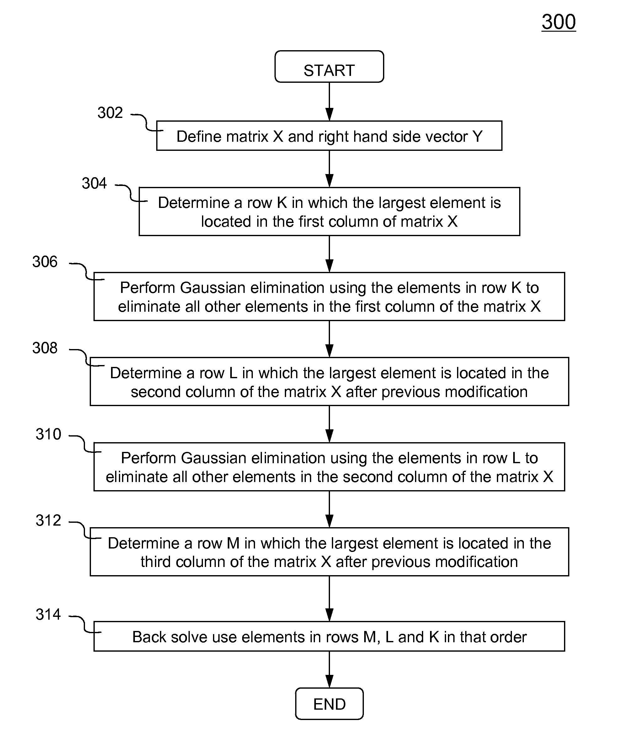
System and method for enabling direct determination of rigid body motion using data collected from a plurality of independent accelerometers are disclosed. A mechanical object that can be theoretically emulated as a rigid body is instrumented with a plurality of accelerometers at different locations. Direct determination of rigid body motion at a location of interest includes following operations at each solution time step: transform local acceleration to global, integrate accelerations to obtain velocities, calculate direction cosine matrix using the angular velocity matrix, form a first set of redundant equations, obtain the angular velocity by solving the first set of equations using either least squares fitting or a selective Gaussian elimination scheme, form a second set of redundant equations and obtain the translational velocity by solving the second set of equations using either the averaged value or a pre-defined rule such as minimizing the contribution from the rotational term.

Description

FIELD OF THE INVENTION[0001]The present invention generally relates to a method, system and software product used in the area of mechanical computer-aided engineering design and analysis, more particularly to direct determination of rigid body motion using data collected from independent accelerometers.BACKGROUND OF THE INVENTION[0002]In physics, a rigid body is an idealization of a solid body of finite size in which deformation is neglected. In other words, the distance between any two given points of a rigid body remains constant regardless of external forces exerted on it. Engineers use rigid bodies to represent mechanical objects or parts (e.g., automobiles, engine blocks, etc) in an engineering analysis or simulation (e.g., finite element analysis). Sometimes, a mechanical part that is relatively rigid compared to the neighboring parts can also be modeled as rigid body. In many instance, simulating dynamic behaviors of a rigid body requires that three-dimensional motions be spe...

Claims


Application Information

Patent Timeline
IPC IPC(8): G01P15/00
CPCG01C21/16G01P3/22G01P3/44G01P7/00G01P15/0888G01C21/166
Inventor SLAVIK, TODD PATRICK
Owner ANSYS
Why Eureka
Try Eureka