System and method of flash memory wear leveling using distributed write cycles

a flash memory and write cycle technology, applied in the field of flash memory storage management and wear leveling, can solve the problems of wasting a large portion of useable memory, reducing the life of particular clusters, etc., and achieves the effect of reducing the number of times of the same area, facilitating the use of all of the memory on the flash chip, and good performan

Inactive Publication Date: 2010-02-02
GENERAL ELECTRIC CO
View PDF9 Cites 19 Cited by
  • Summary
  • Abstract
  • Description
  • Claims
  • Application Information

AI Technical Summary

Benefits of technology

[0003]The wear leveling system and method spreads write cycles across a flash chip, thereby reducing repeated usage of the same areas of the flash chip, and facilitating even usage of all of the memory on the flash chip. When a delete operation occurs in the system and method, the deleted cluster is marked as “dirty” in a table, and the sector address of that cluster is calculated and written into a cache memory. When a write operation occurs, the “dirty” cluster is viewed as a used cluster in order to limit the number of writes to any particular cluster. In a write operation, an unused cluster address is retrieved from a table and a sector address is calculated. If the sector address has a good and low age count, then the write operation writes into the cache memory as well. Before the write operation writes into the cache memory, however, the system and method of the present disclosure checks whether the table requires cleaning and memory updating, or whether a switch to a new table is necessary. Once a purge or sync trigger is effectuated, all of the data written into the cache memory is written into the flash memory.

Problems solved by technology

In frequent delete and write type of operations, the file system uses the same clusters repeatedly and reduces the life of those particular clusters.
When those frequently used clusters no longer function due to overuse, the flash chip must be discarded, thus wasting a large portion of useable memory.

Method used


Image

  • System and method of flash memory wear leveling using distributed write cycles
  • System and method of flash memory wear leveling using distributed write cycles
  • System and method of flash memory wear leveling using distributed write cycles

Examples


Embodiment Construction

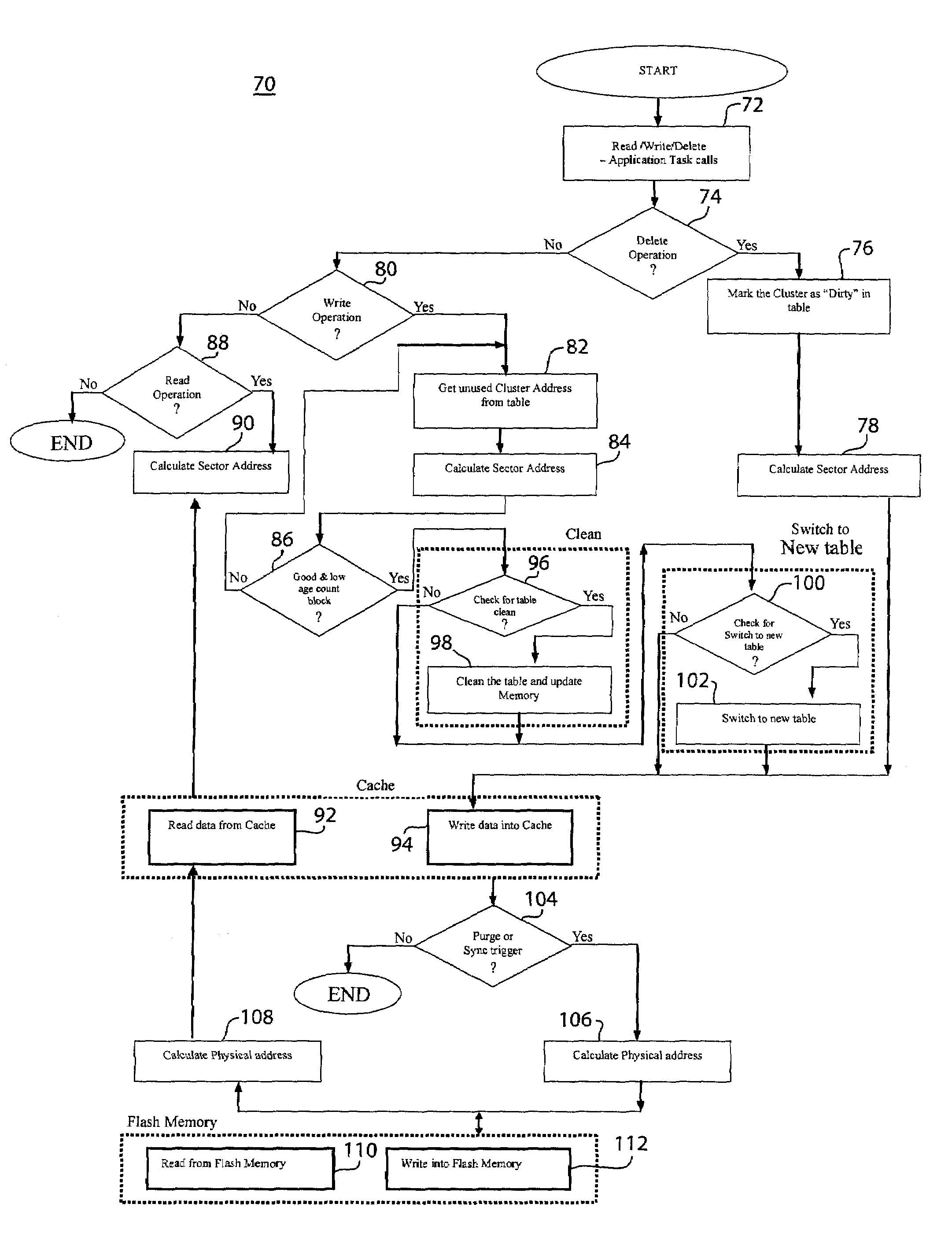
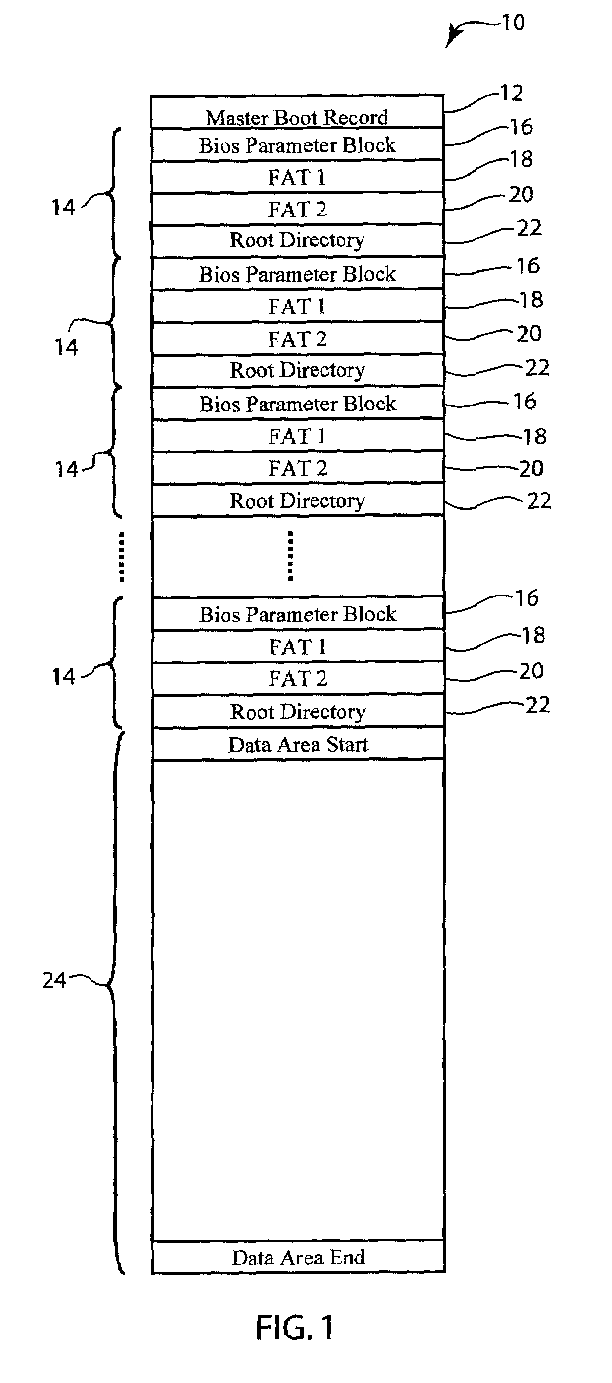
[0014]Referring briefly to FIG. 5, the wear leveling system 48 and method is preferably implemented with a FAT12 file system. It is preferably implemented between a file system 46 layer and a flash memory driver 56. The memory 10 is logically separated into many areas as shown in FIG. 1. The Master Boot record (MBR) 12 holds the starting address of the Table Blocks 14. Preferably, the memory consists of 16 Table Blocks 14; each Table Block 14 including a Bios Parameter Block 16, FAT118, FAT220 and Root Directory 22 areas. The Data Area 24 is mapped after the 16th Table Block 14.

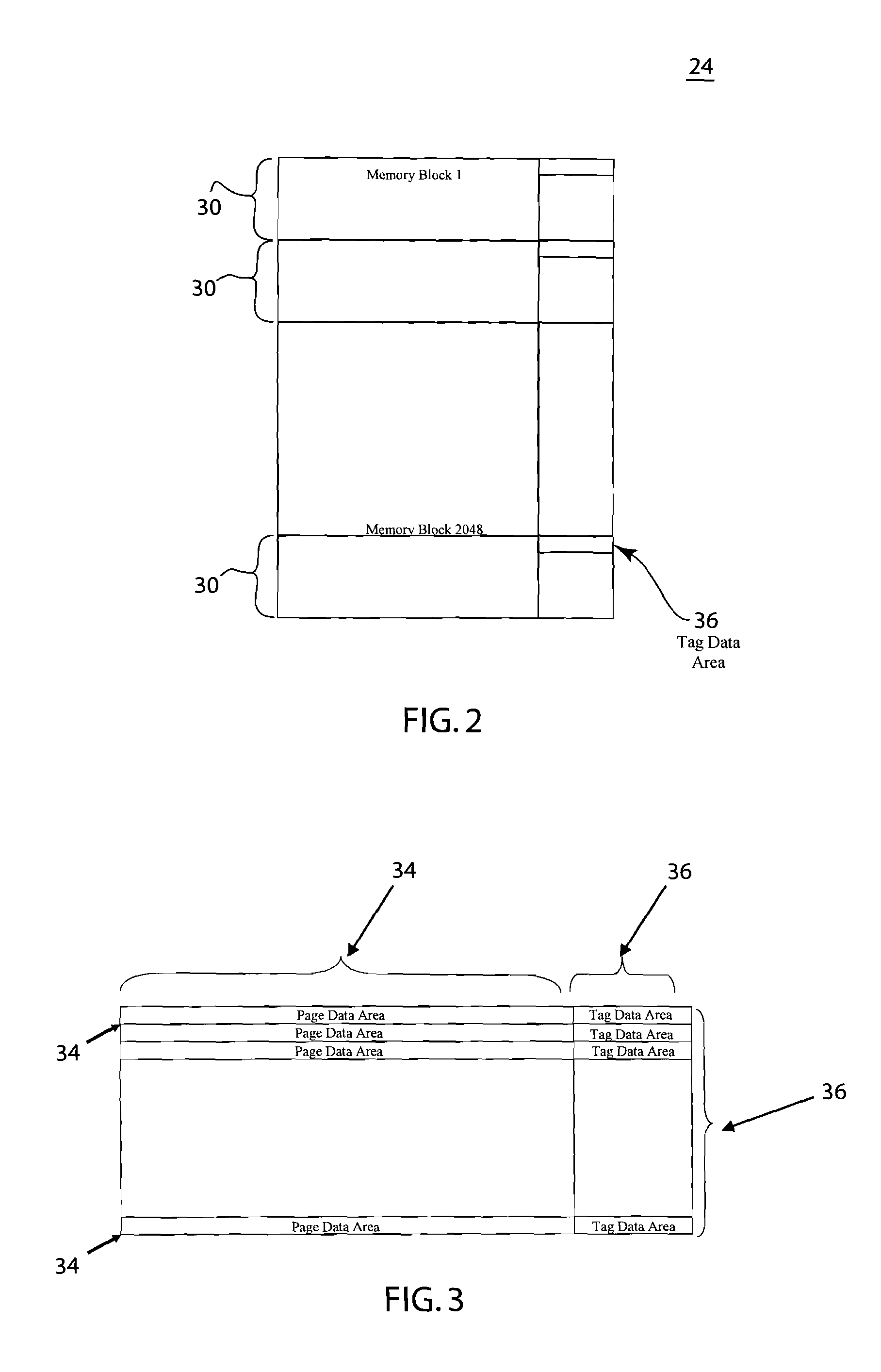
[0015]The physical mapping of the flash chip is shown in FIG. 2. The data area 24 preferably includes 2048 memory blocks 30 and each block 30 has preferably 32 memory pages. Each page has a page data area 34 of 512 bytes and tag data area 36 of 16 bytes. The 512 bytes are used for the file system data and the 16 bytes are used for the flash driver. Referring to both table 1 below and FIG. 4, the erase count, ...


PUM


Abstract

The wear leveling system and method spreads write cycles across a flash chip, thereby reducing repeated usage of the same areas of the flash chip, and facilitating even usage of all of the memory on the flash chip. When a delete operation occurs in the system and method, the deleted cluster is marked as “dirty” in a table, and the sector address of that cluster is calculated and written into a cache memory. When a write operation occurs, the “dirty” cluster is viewed as a used cluster in order to limit the number of writes to any particular cluster. In a write operation, an unused cluster address is retrieved from a table and a sector address is calculated. If the sector address has a good and low age count, then the write operation writes into the cache memory as well. Before the write operation writes into the cache memory, however, the system and method of the present disclosure checks whether the table requires cleaning and memory updating, or whether a switch to a new table is necessary. Once a purge or sync trigger is effectuated, all of the data written into the cache memory is written into the flash memory.

Description

FIELD OF THE DISCLOSURE[0001]The present invention relates to the field of flash memory devices. More particularly, the invention relates to the field of flash memory storage management and wear leveling.BACKGROUND OF THE DISCLOSURE[0002]NAND flash chips are often times used in embedded systems for non-volatile data storage. Generally, a flash chip has a limited number of write cycles, and an embedded system micro controller writes and reads to and from the flash chip. The file system used for data storage manages the storage and retrieval of the data. The data is mapped using cluster numbers and each cluster can have many sectors of 512 bytes. When the file write is performed, the file system checks for the first free cluster and writes the data into that cluster. In frequent delete and write type of operations, the file system uses the same clusters repeatedly and reduces the life of those particular clusters. When those frequently used clusters no longer function due to overuse, ...

Claims


Application Information

Patent Timeline
Patent Type & Authority Patents(United States)
IPC IPC(8): G06F12/00
CPCG06F12/0246G06F12/0804G06F2212/1036G06F2212/7211
Inventor SHANMUGANATHAN, CA
Owner GENERAL ELECTRIC CO
Why Eureka
Try Eureka