
Valve unit of internal combustion engine

a technology of internal combustion engine and valve unit, which is applied in the direction of valve arrangement, machines/engines, mechanical equipment, etc., to achieve the effect of improving the productivity of the internal combustion engin

Active Publication Date: 2010-02-09
MITSUBISHI MOTORS CORP
View PDF15 Cites 2 Cited by
  • Summary
  • Abstract
  • Description
  • Claims
  • Application Information

AI Technical Summary

Benefits of technology

The present invention provides a valve unit for an internal combustion engine that improves productivity. The valve unit includes a camshaft, a variable valve operating mechanism, a sensor, and a retaining member. The sensor detects the rotational displacement of the control shaft and the retaining member fixes the camshaft, the variable valve operating mechanism, and the sensor to the cylinder head. This allows for adjustment of cylinder-to-cylinder variation using a simulation system and facilitates maintenance. The valve unit also includes an adjustment mechanism for adjusting the valve drive output for each cylinder and a sensor arrangement at the axial end of the control shaft. The retaining member includes a holder member, a cap member, and a fixing bolt member that penetrate the holder member and the cap member and can be screwed into the cylinder head. The invention provides additional objects and advantages such as improved productivity and efficiency.

Problems solved by technology

The cylinder-to-cylinder variation adjustment work and the troublesome work for attaching the sensor and adjusting the sensor, which become factors causing stagnation on the main line, are made unnecessary.

Method used


Image

  • Valve unit of internal combustion engine
  • Valve unit of internal combustion engine
  • Valve unit of internal combustion engine

Examples


Embodiment Construction

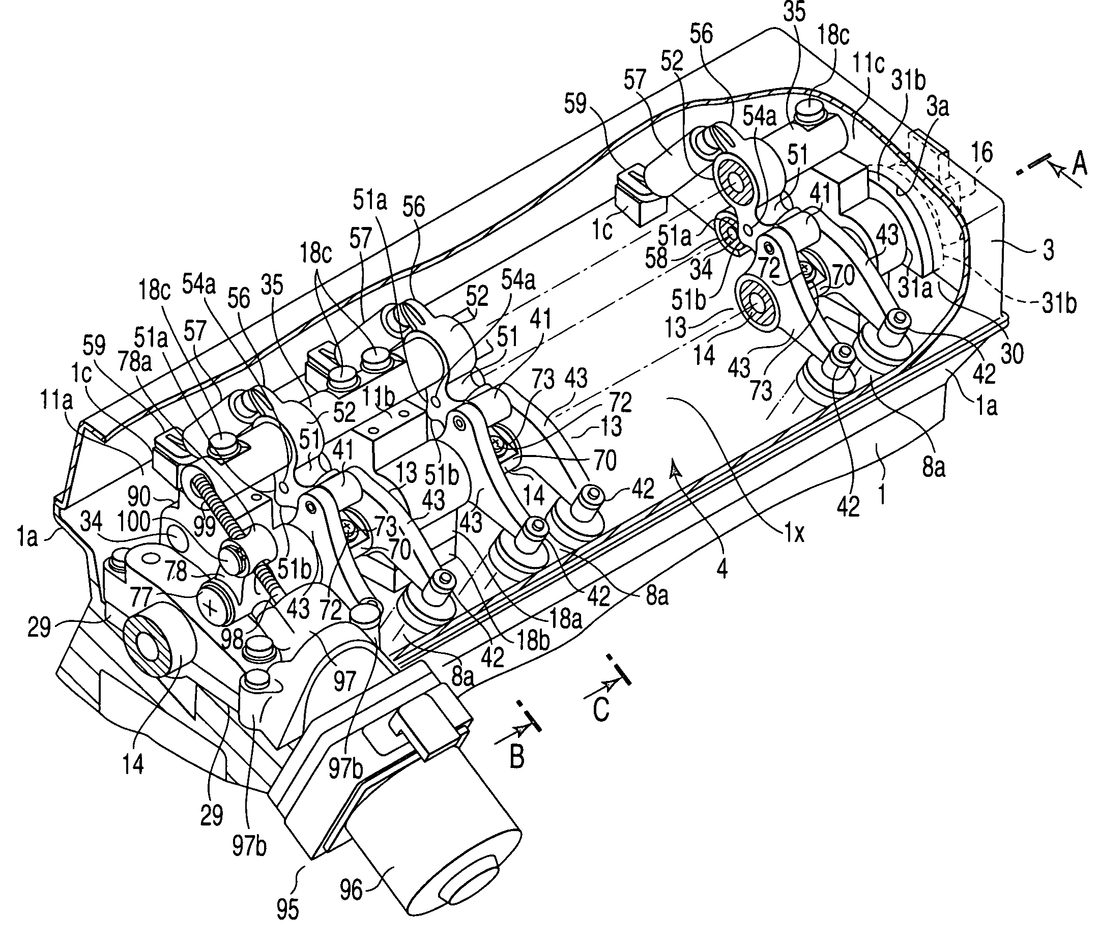
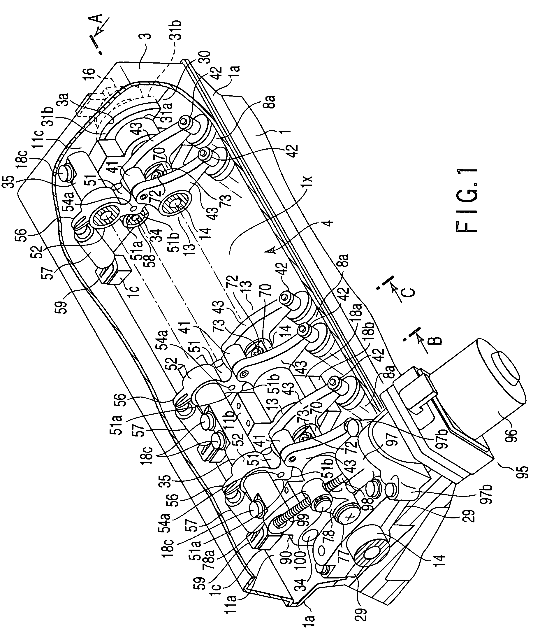
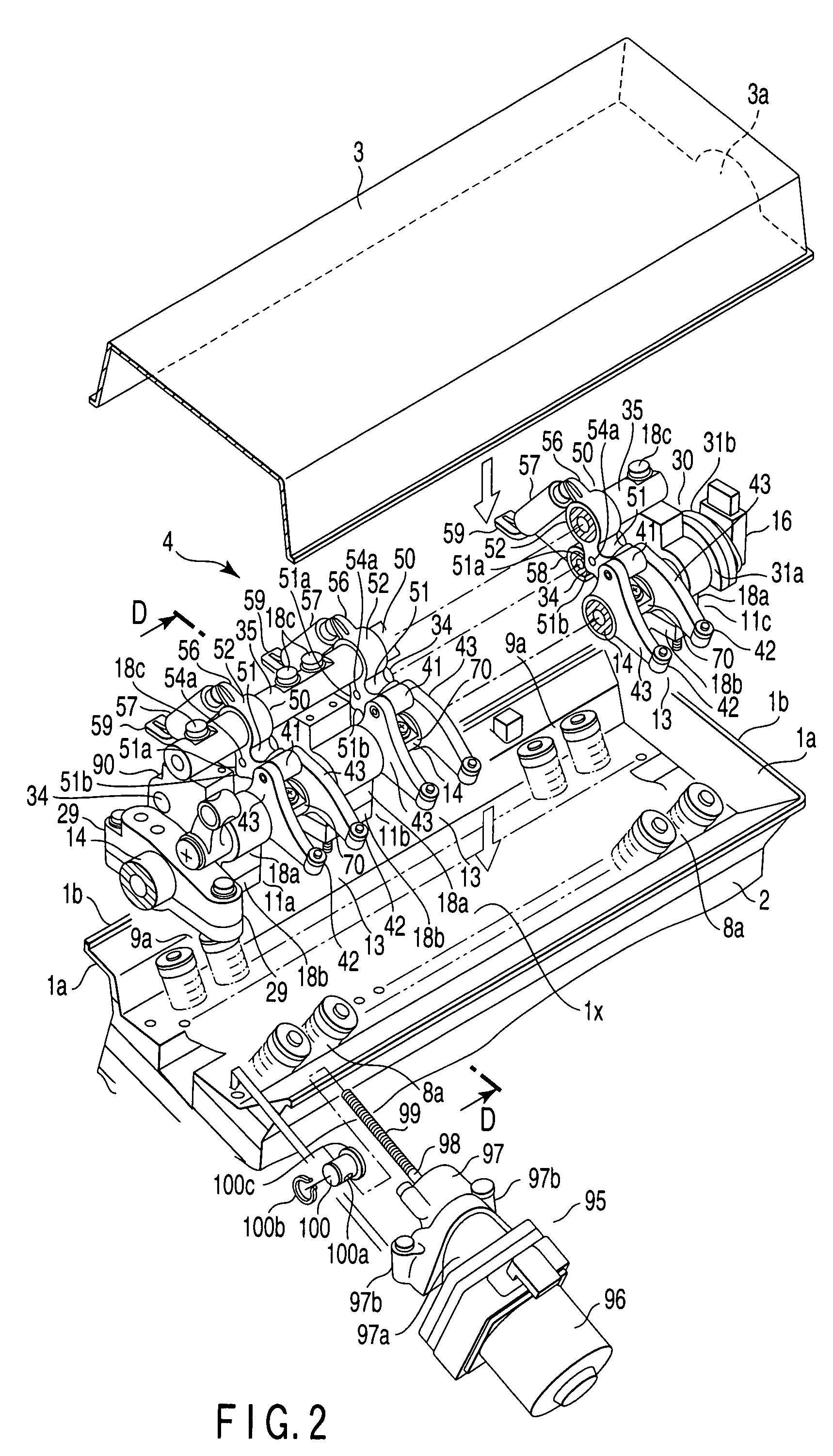
[0031]A variable valve unit of an internal combustion engine according to a first embodiment of the present invention will be described below with reference to FIGS. 1 to 7. FIG. 1 shows a perspective view of a head part of an engine main body in a reciprocating inline four-cylinder petrol engine, which is an example of a multicylinder internal combustion engine. FIG. 2 is a perspective view showing a state where the head part is disassembled. FIGS. 4 to 7 are cross-sectional views respectively showing states where respective parts (cross sections taken along lines A, B, and-C in FIG. 1, and line D-D in FIG. 2) are cross-sectioned.

[0032]A reference numeral 1 in FIG. 1 denotes a cylinder head mounted on a head part of a cylinder block 2 (shown in only FIG. 5 by two-dot chain lines). A reference numeral 3 denotes a rocker cover covering an upper part of the cylinder head 1. A reference numeral 4 denotes SOHC type variable valve unit which is in a space between the cylinder head 2 and ...


PUM


Abstract

A valve unit of an internal combustion engine is accommodated in a space between a cylinder head and a rocker cover. The valve unit comprises a camshaft, a variable valve operating mechanism, a sensor, and a retaining member. The camshaft is provided with a cam for each cylinder. The variable valve operating mechanism receives a displacement of the cam, outputs a valve drive output, and continuously variable-controls the valve drive output in accordance with a rotational displacement of a control shaft provided substantially in parallel with the camshaft. The sensor detects the rotational displacement of the control shaft. The retaining member retains the camshaft, the variable valve operating mechanism, and the sensor. The retaining member expose the sensor to the out side of the rocker cover thereby to fix the camshaft, the variable valve operating mechanism, and the sensor to the cylinder head.

Description

CROSS-REFERENCE TO RELATED APPLICATIONS[0001]This application is based upon and claims the benefit of priority from prior Japanese Patent Application No. 2006-297044, filed Oct. 31, 2006, the entire contents of which are incorporated herein by reference.BACKGROUND OF THE INVENTION[0002]1. Field of the Invention[0003]The present invention relates to a valve unit of an internal combustion engine in which a valve characteristic of an intake valve or an exhaust valve is continuously controlled.[0004]2. Description of the Related Art[0005]In a valve unit of a multicylinder reciprocating engine (internal combustion engine) mounted on an automobile, in order to reduce fuel consumption by exhaust gas measures or by improving pumping loss, a variable valve in which a characteristic of an intake valve (or an exhaust valve) is continuously and variably controlled is incorporated in a head part of a cylinder head covered with a rocker cover.[0006]In most variable valve units, a structure is use...

Claims


Application Information

Patent Timeline
Patent Type & Authority Patents(United States)
IPC IPC(8): F01L1/34
CPCF01L13/0063F01L2001/0535F01L2013/0068F01L2820/032F01L1/18F01L1/255F01L13/00
Inventor TANABE, MIKIOMURATA, SHINICHITODA, HITOSHIIGARASHI, MASASHI
Owner MITSUBISHI MOTORS CORP
Learn More