Skin treatment system and method of use

a skin treatment and skin technology, applied in the field of skin treatment and conditioning, can solve the problems of inability to effectively perform microabrasion, difficulty in accurately controlling the amount of tissue, and the amount and rate of tissues removed

Inactive Publication Date: 2010-02-09
ENVY MEDICAL
View PDF77 Cites 51 Cited by
  • Summary
  • Abstract
  • Description
  • Claims
  • Application Information

AI Technical Summary

Benefits of technology

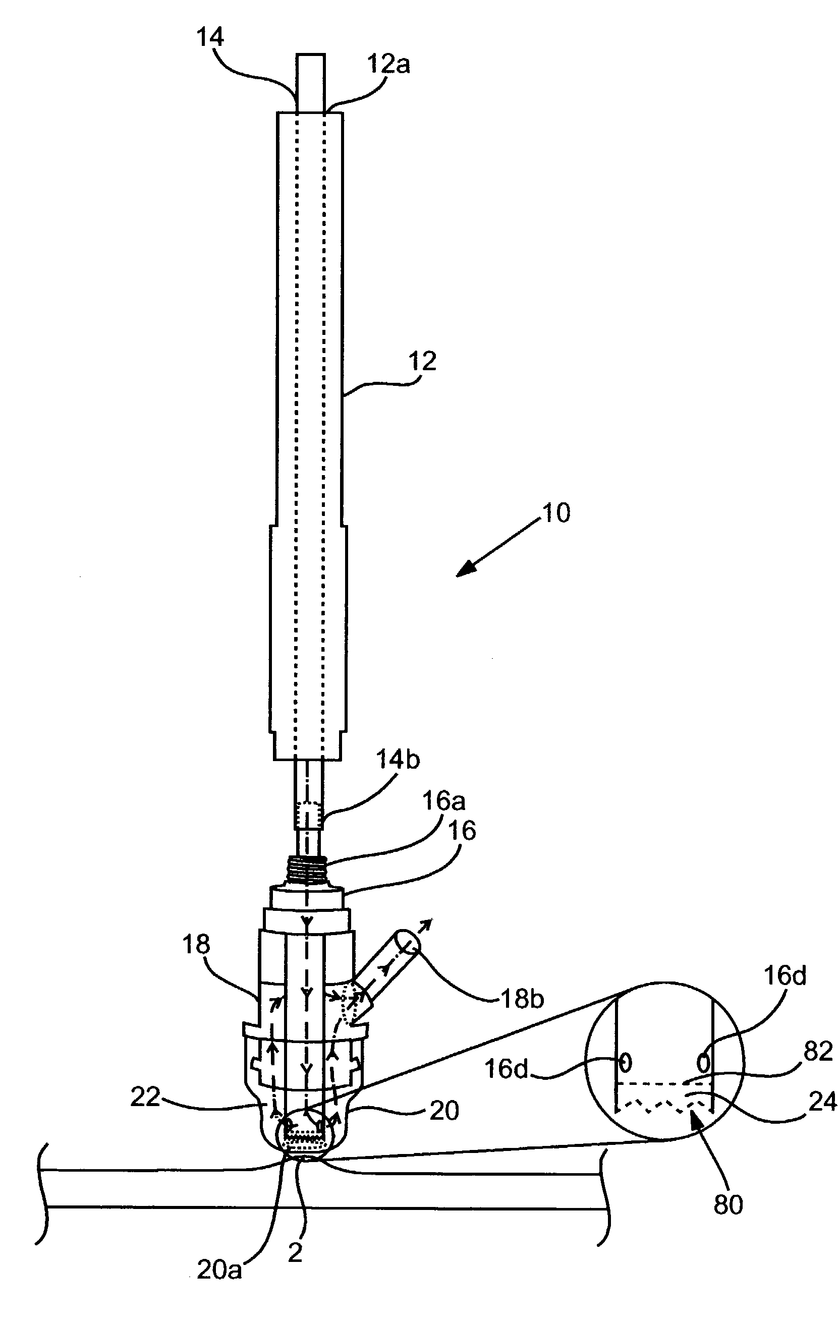
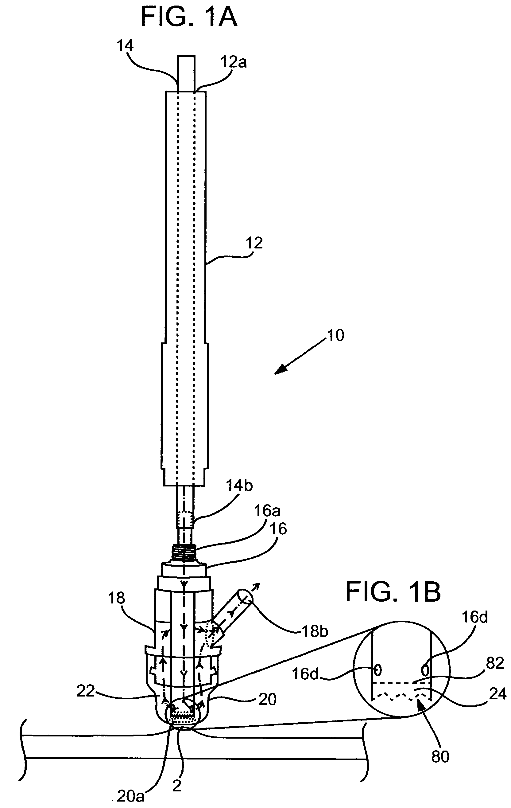
[0019]The abrasive member or a non-abrasive member seals off the end of the conduit which is located internally of the applicator tool, and at least one opening is provided through a wall of the conduit. In either case, the member that seals off the conduit is positioned relative to the tip opening to serve as a limiting surface with respect to tissue drawn into the device by vacuum. The abrasive member is textured to enable microdermabrasion. The non-abrasive member preferably has a surface finish that avoids such action. Still, the system may be provided with a conduit sealing member of any of a range or spectrum of abrasiveness ranging from (substantially) zero, to a maximum level suited for microdermabrasion. To maximize device utility, the sealing member is preferably removable / interchangeable with others to offer a variety of functions and / or treatment options.
[0024]The vacuum provided by the negative pressure surrounds a perimeter of the abrasive, moderately abrasive or non-abrasive conduit seal member. In a microabrasion application, this makes it so that microabraded skin particles are collected downstream of the abrasive member and from all locations surrounding the abrasive member. In other applications (but also in microdermabrasion), such an arrangement assists in the ability to move the device in any direction over the skin. The symmetric nature of the configuration avoids such need as experienced with other implements that have a certain directionality requirement (i.e., they must “point” in their direction of travel). In a microdermabrasion application, the inventive device configuration provides for applying not only any abrasive compounds as may be desired directly and immediately at the spot of abrasion, but also (or alternatively) other solutions or compounds offering various benefit(s).

Problems solved by technology

This device is more properly referred to as a dermabrasion device as it is quite aggressive in the amounts and rates of tissues removed.
While this type of device can be effective for removing gross scarring and keloids such as those associated with burn victims, it can also cause scarring and is difficult to accurately control with regard to amounts of tissue removed.
As such it is incapable of effectively performing microabrasion as it is currently defined in the art.
U.S. Pat. No. 2,867,214 similarly discloses a device that employs motor driven stainless steel wire brushes and cannot effectively perform microdermabrasion.
U.S. Pat. No. 4,241,499 discloses a hand held foot care instrument that includes a roughened dermabrasion undersurface to function as a nail file and skin smoother While this device may be effective for “spot treatment” of calluses, corns and the like on the foot, it would not be an effective tool for an overall microdermabrasion treatment of the face or other large area of skin that must be treated with a consistent amount of abrasion over an entire surface.
No means are disclosed for conditioning the skin or of removing the dead skin particles from the surface of the skin after they have been abraded.
However, a trailing side of the abrasive tip, which trails the central opening of the abrasive tip as the tip is moved over the surface of the skin, also microabrades the skin surface and leaves a trail of loosened skin particles which cannot be collected by the vacuum.
Additionally, this is a dry system which does not treat the skin during microdermabrasion, which can leave streaking effects on the remaining skin.
For example, no instrument or system adapted to perform microderabrasion includes provision for delivery of a therapeutically useful solution at the abraded site.

Method used


Image

  • Skin treatment system and method of use
  • Skin treatment system and method of use
  • Skin treatment system and method of use

Examples


Embodiment Construction

[0036]Before the present device, system and methods are described, it is to be understood that this invention is not limited to particular structures described, as such may, of course, vary. It is also to be understood that the terminology used herein is for the purpose of describing particular embodiments only, and is not intended to be limiting, since the scope of the present invention will be limited only by the appended claims.

[0037]Where a range of values is provided, it is understood that each intervening value, to the tenth of the unit of the lower limit unless the context clearly dictates otherwise, between the upper and lower limits of that range is also specifically disclosed. Each smaller range between any stated value or intervening value in a stated range and any other stated or intervening value in that stated range is encompassed within the invention. The upper and lower limits of these smaller ranges may independently be included or excluded in the range, and each ra...


PUM


Abstract

A device, a system employing the device and method of performing skin treatment are provided for skin treatment. The device includes a vacuum head base defining a chamber therein and having a substantially smooth treatment tip attached and extending from an end thereof or integral therewith. The tip has at least one central opening that is open to the chamber, and is adapted to contact the skin and traverse the skin in a substantially non-abrasive manner. A vacuum access opening is provided through a side wall of the vacuum head base and adapted to connect with a source of vacuum. A tissue stop member is located within the chamber. It may have an abrasive surface for exfoliating skin cells, or a smoother surface for traversing the skin without substantial abrasion.

Description

CROSS-REFERENCE TO RELATED APPLICATION[0001]This application is a continuation-in-part of U.S. patent application Ser. No. 09 / 989,992, filed on Nov. 21, 2001, now issued as U.S. Pat. No. 6,695,853 on Feb. 24, 2004.FIELD OF THE INVENTION[0002]The present invention pertains to dermatology, more particularly to skin treatment and conditioning.BACKGROUND OF THE INVENTION[0003]Microdermabrasion is a process for removing dead cells from the outermost layer of the skin (the epidermis) to provide a younger and healthier looking appearance, remove wrinkles, clean out blocked pores, remove some types of undesirable skin conditions that can develop, and enhance skin tone. The process of microdermabrasion must be performed with a certain degree of accuracy, so that underlying live layers of skin tissue are not removed or damaged, but that enough dead cells are removed to give effective results.[0004]Abrasive tipped devices or rotating brushes and cylinders coated with abrasive particles, such a...

Claims


Application Information

Patent Timeline
Patent Type & Authority Patents(United States)
IPC IPC(8): A61M1/00A61B17/50A61BA61B17/00A61B17/32A61B17/54B24C3/06B24C7/00
CPCA61B17/54A61B17/32B24C3/065B24C7/0046A61B17/545A61B2017/00761A61B2017/320004A61B2217/007A61B2217/005
Inventor KARASIUK, KENNETH B.
Owner ENVY MEDICAL
Why Eureka
Try Eureka