Particle beam irradiation system

a particle beam and irradiation system technology, applied in the field of particle beam irradiation system, can solve the problems of requiring a more tedious and time-consuming accuracy control task, occupying a larger space, and requiring a large space, so as to achieve easy accuracy control, simple structure, and occupy a small space

Inactive Publication Date: 2010-02-09
UEMATSU MINORU +2
View PDF17 Cites 53 Cited by
  • Summary
  • Abstract
  • Description
  • Claims
  • Application Information

AI Technical Summary

Benefits of technology

[0007]An object of the present invention is to provide a particle beam irradiation system which includes a particle beam irradiation apparatus free of a rotary gantry structure, is capable of multiple field irradiation, has an overall simple structure, takes up a small space, is placed under easy accuracy control, can be manufactured at a low cost, and is capable of irradiating the affected area of a patient with a particle beam from many directions with high positional accuracy.
[0008]The present inventor has made intensive and extensive investigations in order to attain the above object. As a result of the investigations, it has been found out that, a particle beam irradiation system has a particle beam irradiation apparatus which is free of a rotating gantry structure and which irradiates a particle beam in one direction, and for irradiating the affected area of the patient with the particle beam, the patient rotates, so that the particle beam irradiation system can irradiate the particle beam from various direction, as in the case using the rotating gantry structure. For example, as conceptionally shown in FIG. 2, the irradiation direction of the irradiation apparatus 1 is fixed, the particle beam 1a is applied in one direction, preferably obliquely from a position above the human (the patient) 3 and the patient 3 is rotated, furthermore, for example, as conceptionally shown in FIGS. 3A through 3C, the patient fixing device 4 for fixing the patient (not shown in FIGS. 3A through 3C) is rotatable (tiltable) with respect to the floor surface (ground surface) G. With this construction, it is possible to change the irradiation angle of the particle beam 1a applied in one direction with respect to the affected area 3a of the patient (not shown in FIGS. 3A through 3C) fixed by the patient fixing device 4, so that it is capable of irradiating the affected area of the patient with the particle beam from many directions. Furthermore, for example, as shown in FIGS. 3A through 3C, the CT scanner 2 and the patient fixing device 4 are tiltable at the same angle with respect to the floor surface (ground surface) G, so that, as shown in FIG. 3B, when the patient fixing device 4 is in the state that is tilt with respect to the floor surface (ground surface) G, the patient fixing device 4 is inserted in the detection range 2a of CT scanner 2 at the tilt angle as is and the CT scanning is possible in the tilt state. The above object is attained by the construction in which the patient fixing device is rotated or moved so that it is possible to irradiate the affected area of the patient with the particle beam from many directions, by the patient fixing device which is movable between the particle beam irradiation apparatus and the CT scanner and the positionally confirming the affected area of the patient rotated or moved is possible.
[0010]With this configuration, it is possible to accurately confirm the position of the affected area of the patient with the CT scanner from any of various angles and irradiate an affected area from any of various angles by combining the rotary motion of the patient fixing device with movement of the drive unit and the rotary motion of the housing unit.
[0012]With this configuration, it is possible to set the patient's body to more comfortable posture (physique) while the patient fixing device is rotated (tilted) to allow the particle beam irradiation apparatus to apply the particle beam to the affected area of the patient from many directions.
[0014]With this configuration, it becomes easy to irradiate the affected area of the patient with a particle beam accurately even if the patient fixing device is rotated and when the CT scanner confirms the position of the affected area of the patient, the movement of the patient fixing device between the irradiation apparatus and the CT scanner becomes easy.

Problems solved by technology

However, it is much more technically challenging, takes up a larger space, requires a more tedious and time-consuming accuracy control task, and is much more costly to construct a rotary gantry structure which incorporates an apparatus for applying a proton beam or a heavy ion beam than an apparatus for applying an X-ray.
Even a proton beam or a heavy ion beam is not effective enough if applied to the patient in one direction only.

Method used


Image

  • Particle beam irradiation system
  • Particle beam irradiation system
  • Particle beam irradiation system

Examples


Embodiment Construction

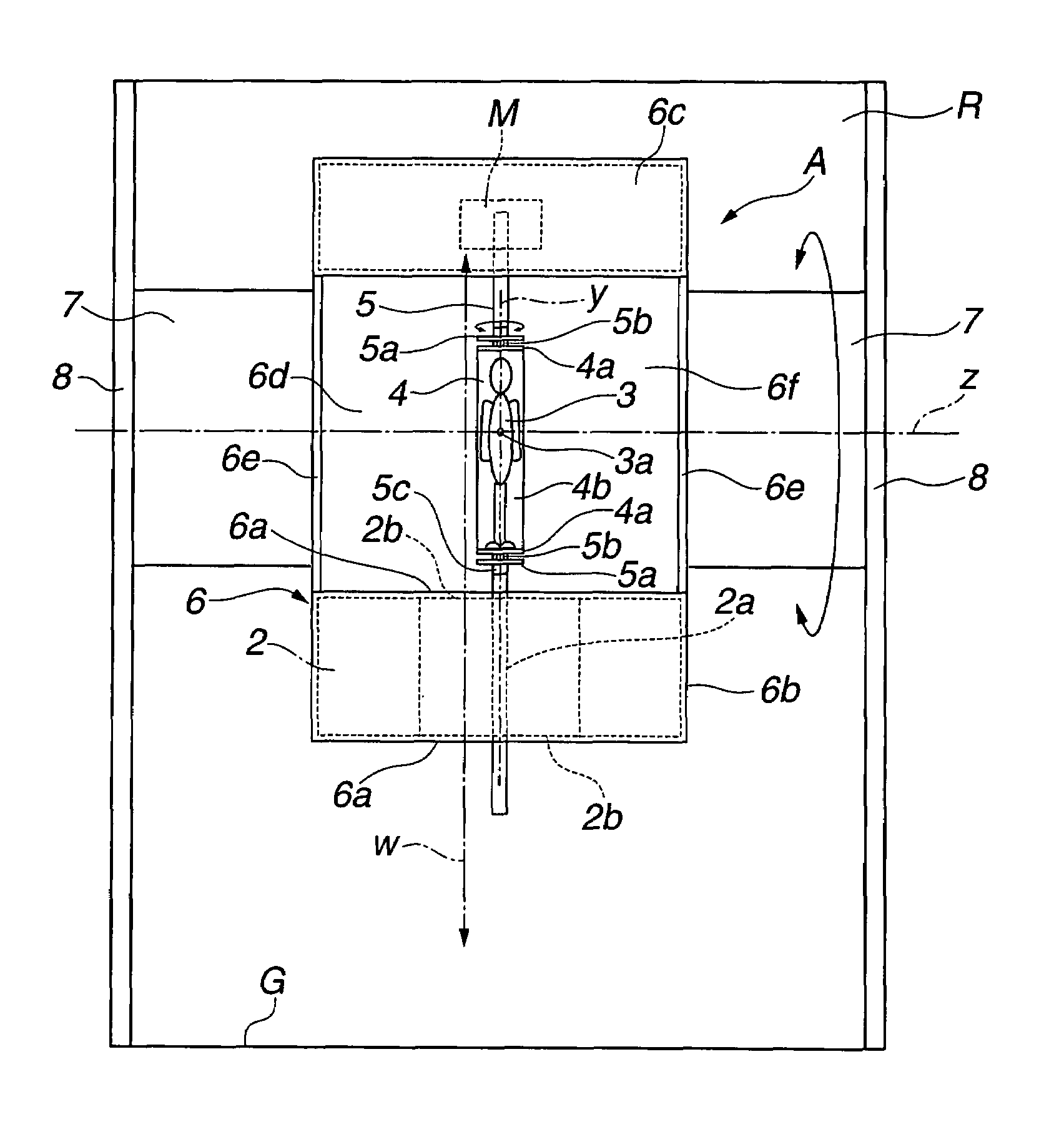
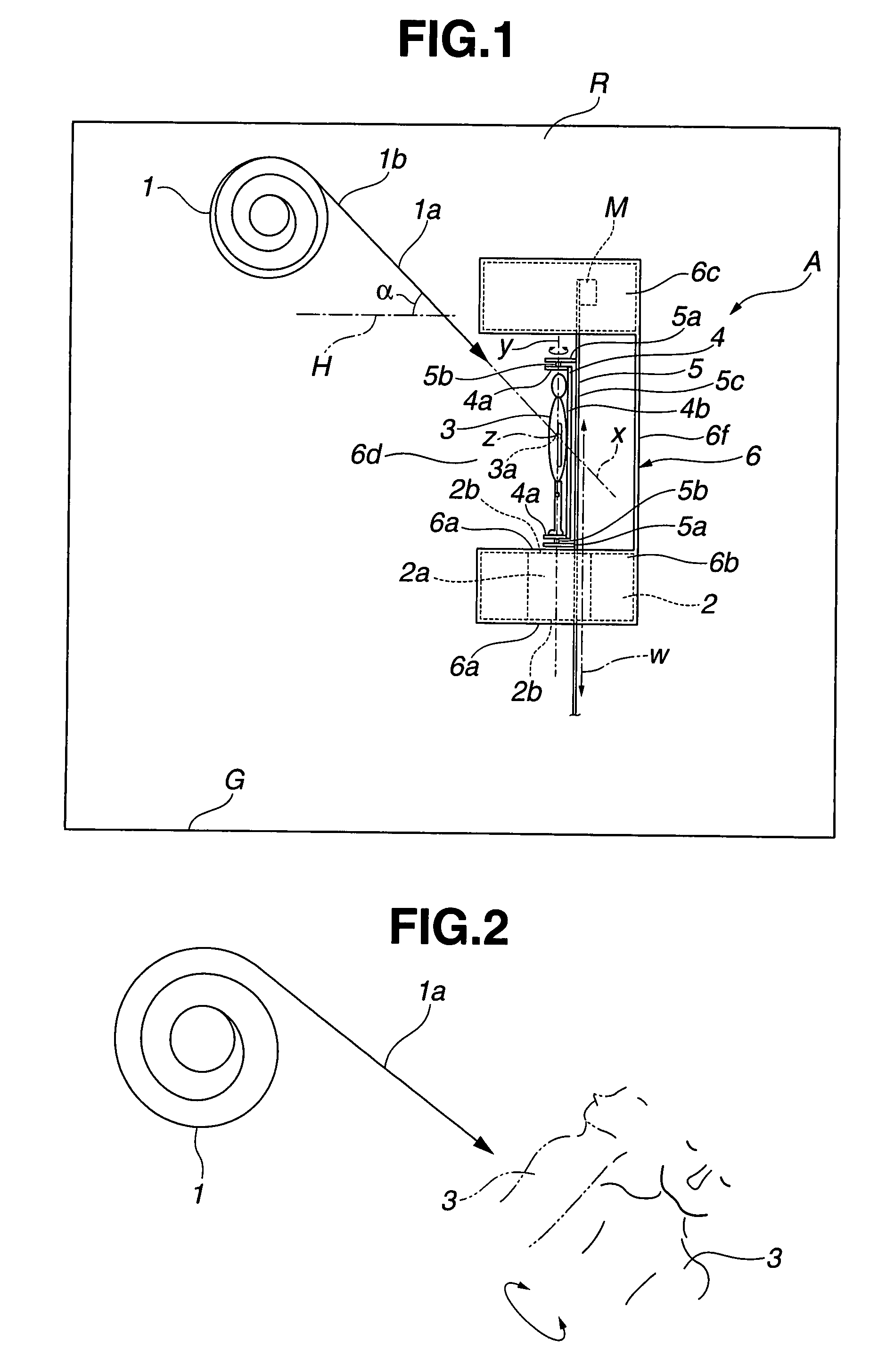
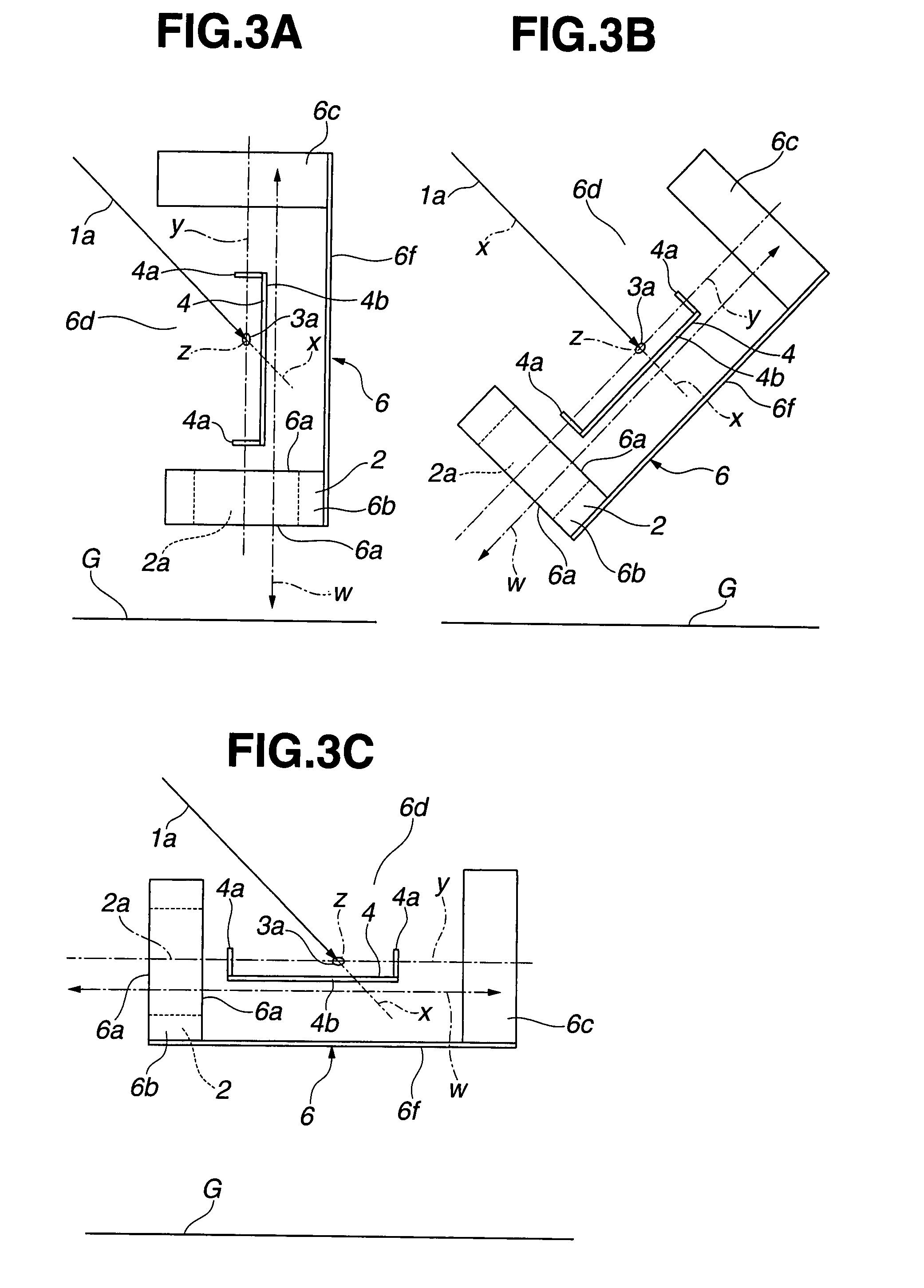
[0020]A particle beam irradiation system according to an embodiment of the present invention will be described in detail below with reference to the drawings. FIG. 1 shows in schematic side elevation the particle beam irradiation system according to an embodiment of the present invention. As shown in FIG. 1, the particle beam irradiation system, generally designated by A, is installed in a treatment chamber R and includes a particle beam irradiation apparatus 1, a CT scanner 2, a patient fixing device 4 for fixing a patient 4, a drive unit 5 for moving the patient fixing device 4 between an irradiation range of the particle beam irradiation apparatus 1 and a detection range 2a of the CT scanner 2, and a housing unit 6 storing therein the CT scanner 2 and the drive unit 5 with the patient fixing device 4 mounted thereon. The housing unit 6 has opposite side walls which are positioned on the sides of the housing unit 6 that are respectively closer to and remoter from the viewer of FIG...


PUM


Abstract

A particle beam irradiation system includes a particle beam irradiation apparatus, which is free of a gantry structure, having a particle beam irradiator for irradiating an affected area of a patient with a particle beam, the particle beam irradiator being housed in a chamber, a CT scanner installed in the chamber, for positionally confirming the affected area of the patient, a drive unit for moving the patient from a detection range to an irradiation range, a patient fixing device for fixing the patient in position, the device being mounted on the drive unit for rotation, and a housing unit having a structure housing the drive unit with the patient fixing device mounted and the CT scanner, the housing unit being rotatable about an axis perpendicular to a plane including a direction in which the particle beam is applied and a direction in which the drive unit moves.

Description

BACKGROUND OF THE INVENTION[0001]1. Field of the Invention[0002]The present invention relates to a particle beam irradiation system for accurately irradiating the affected area of a patient with a particle beam such as a proton beam, a heavy ion beam, or the like, or more particularly to a particle beam irradiation system having a particle beam irradiation apparatus which is free of a rotating gantry structure and which radiates a particle beam from one direction, so that the particle beam irradiation system can be reduced in overall size and cost, and the particle beam irradiation apparatus has its accuracy control made easy. The particle beam irradiation system according to an embodiment of the present invention has a unit structure housing a CT scanner and a drive unit in integral combination, the CT scanner being installed in a treatment chamber for accurately confirming the position of the affected area of the patient and the drive unit being integrally combined with the CT sca...

Claims


Application Information

Patent Timeline
Patent Type & Authority Patents(United States)
IPC IPC(8): H05G1/02A61N5/00
CPCA61N5/1049A61N5/1078A61N2005/1061A61N2005/1063
Inventor UEMATSU, MINORU
Owner UEMATSU MINORU
Why Eureka
Try Eureka