Alignment method for parabolic trough solar concentrators

a technology of parabolic trough and solar concentrator, which is applied in the field of solar collectors, can solve the problems of inability to develop practical optical alignment techniques for accurate alignment of parabolic trough concentrators, preventing maximum energy efficiency, and lack of accuracy, so as to reduce spillage losses, enable the best possible optical performance, and align the effect of accuracy

Active Publication Date: 2010-02-23
NAT TECH & ENG SOLUTIONS OF SANDIA LLC
View PDF6 Cites 51 Cited by
  • Summary
  • Abstract
  • Description
  • Claims
  • Application Information

AI Technical Summary

Benefits of technology

[0013]The TOP alignment method of the present invention satisfies all of the requirements of a desired alignment process. It uses relatively low technology equipment, inherently aligns the mirrors to the HCE, and can be implemented day or night within the rows of commercial trough power plants. It is also adaptable for use in new installations, mirror replacement, and for characterizing gravity-induced optical errors. Alignment accuracy should be better than t

Problems solved by technology

However, a problem with trough concentrators has been the lack of accurate mirror facet alignment, preventing maximum energy efficiency.
Compared with parabolic dish concentrators, practical optical alignment techniques for the accurate alignment of parabolic trough concentrators have not been developed.
The relatively short focal lengths and low operating temperature in parabolic trough systems have allowed them to be developed and commercialized with relatively inaccurate alignment by the use of fixtures.
Their linear nature has also been a barrier to the development of practical optical techniques.
Accurate alignment of concentrating collectors by the use of fixtures is extremely difficult.
Error stack-up and indeterminate effects, such as

Method used


Image

  • Alignment method for parabolic trough solar concentrators
  • Alignment method for parabolic trough solar concentrators
  • Alignment method for parabolic trough solar concentrators

Examples


Embodiment Construction

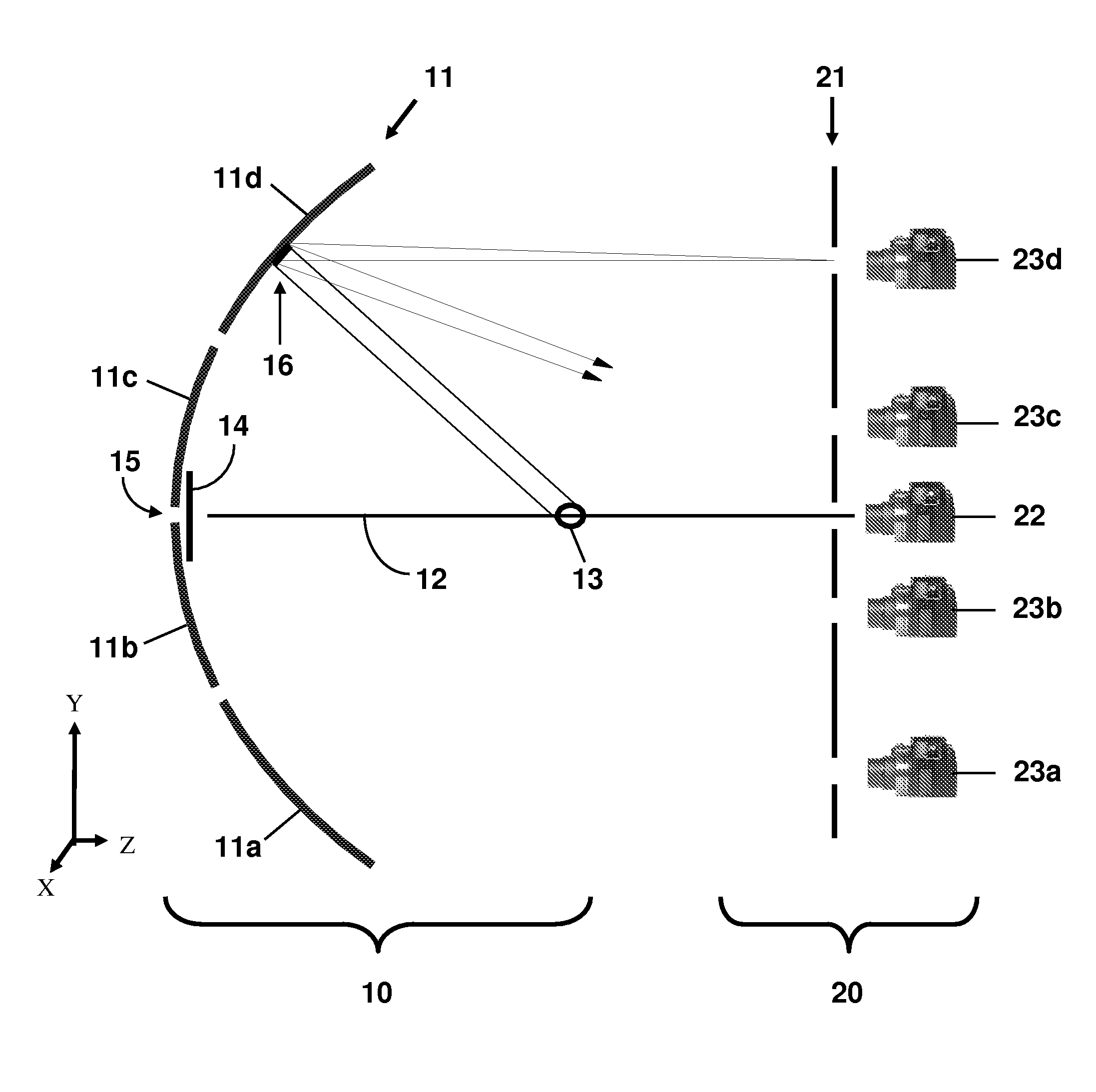
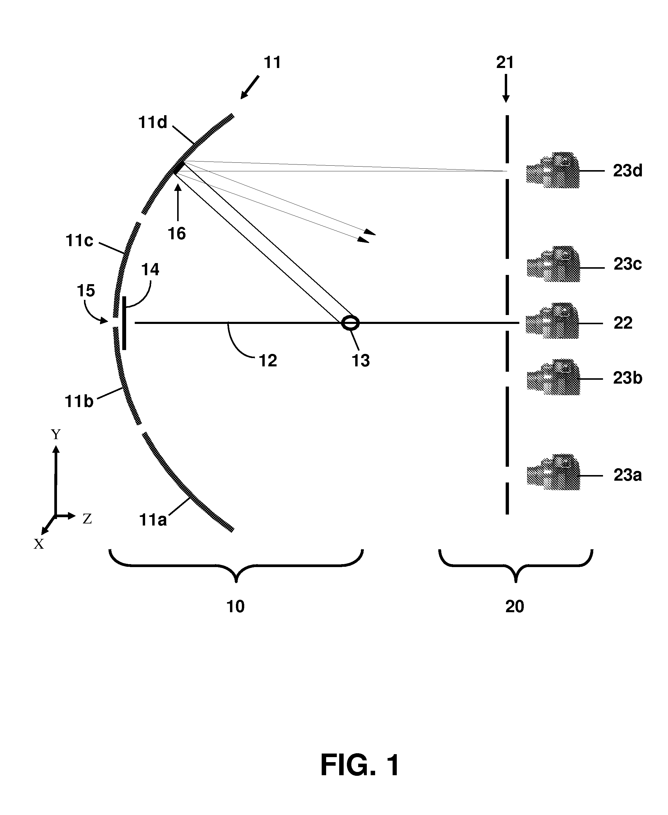
[0021]In FIG. 1 is shown a side-view schematic illustration of a parabolic collector 10 that illustrates the basic principles of the TOP alignment method of the present invention. The collector 10 comprises a line-focusing parabolic trough concentrator 11 and a linear receiver, or HCE 13. The parabolic axis 12 lies in the z direction, through the vertex 15 of the trough concentrator 11. Elevation is in the vertical y direction. The trough of the concentrator 11 and the length of the HCE 13 run in the horizontal x direction, out of the plane of the figure. The trough concentrator 11 comprises at least two rows of mirror facets.

[0022]Each row comprises one or more mirror facets that are arranged serially in the x direction. For example, four rows 11a-d of mirror facets are shown in FIG. 1. Adjacent mirror facets in adjacent rows can be arranged in columns. The rows and columns of mirror facets form a concentrator module 11. Light from a source (e.g., the sun) is reflected by the rows ...


PUM


Abstract

A Theoretical Overlay Photographic (TOP) alignment method uses the overlay of a theoretical projected image of a perfectly aligned concentrator on a photographic image of the concentrator to align the mirror facets of a parabolic trough solar concentrator. The alignment method is practical and straightforward, and inherently aligns the mirror facets to the receiver. When integrated with clinometer measurements for which gravity and mechanical drag effects have been accounted for and which are made in a manner and location consistent with the alignment method, all of the mirrors on a common drive can be aligned and optimized for any concentrator orientation.

Description

CROSS-REFERENCE TO RELATED APPLICATION[0001]This application claims the benefit of U.S. Provisional Application No. 60 / 817,160, filed Jun. 28, 2006, which is incorporated herein by reference.STATEMENT OF GOVERNMENT INTEREST[0002]This invention was made with Government support under contract no. DE-AC04-94AL85000 awarded by the U.S. Department of Energy to Sandia Corporation. The Government has certain rights in the invention.FIELD OF THE INVENTION[0003]The present invention relates to solar collectors and, in particular, to alignment methods for parabolic trough solar concentrators that overlays a theoretical projected image on a photographic image of the receiver and adjusts the mirror facets of the trough concentrator until the images coincide.BACKGROUND OF THE INVENTION[0004]Parabolic trough solar concentrators use mirrored surfaces curved in a parabolic shape. The mirrors focus sunlight on a receiver tube, or heat collection element (HCE), running the length of the trough. In a ...

Claims


Application Information

Patent Timeline
IPC IPC(8): G01B11/26
CPCF24J2/14F24J2/407G01B11/26F24J2002/385Y02E10/45F24S23/74F24S50/80F24S2050/25Y02E10/40
Inventor DIVER, RICHARD B.
Owner NAT TECH & ENG SOLUTIONS OF SANDIA LLC
Why Eureka
Try Eureka