
Electrolytic capacitor

a capacitor and electrolytic technology, applied in the field of electrolytic solution, can solve the problems of insufficient specific resistance of recent small electrolytic capacitors, inability to advantageously use electrolytic capacitors as electronic parts, and inferior noise removal ability and charging/discharging efficiency of conventional electrolytic solution, etc., to achieve excellent noise removal ability and charging and discharging efficiency, and reduce the equivalent series resistance of capacitors

Active Publication Date: 2010-02-23
RUBYCON CORPORATION
View PDF33 Cites 4 Cited by
  • Summary
  • Abstract
  • Description
  • Claims
  • Application Information

AI Technical Summary

Benefits of technology

[0012]An object of the present invention is to solve the above problems of the prior art and to thereby decrease equivalent series resistance (ESR) of the capacitor, and thus provide an electrolytic solution for use in an electrolytic capacitor which is excellent in noise removing ability and charging and discharging efficiency and is also capable of realizing an electrolytic capacitor having the ideal characteristics for electronic parts.
[0013]More particularly, a first object of the present invention is to provide an electrolytic solution, for use in an electrolytic capacitor, capable of realizing an electrolytic capacitor which shows excellent and stable electrical characteristics in a wide temperature range from a low temperature just above the freezing temperature to high temperature and also causes little change in ESR.
[0014]A second object of the present invention is to provide a flame-retardant, safe and cheap electrolytic solution for use in an electrolytic capacitor by suppressing the use of an expensive organic solvent as much as possible.
[0015]A third object of the present invention is to provide an electrolytic solution, for use in an electrolytic capacitor, capable of realizing a long working life by controlling the total content of an electrolyte thereby to suppress a vigorous reaction with an electrode foil.
[0016]A fourth object of the present invention is to provide an electrolytic capacitor which shows low ESR and also shows excellent and stable electrical characteristics in a wide temperature range from a low temperature just above the freezing temperature to high temperature.
[0017]A fifth object of the present invention is to provide an electrolytic capacitor which causes neither swelling nor liquid leakage from the case containing a capacitor element and is excellent in airtightness and sealing strength, and is also excellent in working life at a high temperature.

Problems solved by technology

Such a specific resistance is insufficient for recent small, high-performance electrolytic capacitors.
For example, a conventional electrolytic solution is inferior in noise removing ability and in charging / discharging efficiency because the equivalent series resistance (ESR) of a capacitor cannot be decreased sufficiently.
Therefore, the resulting electrolytic capacitor cannot be used advantageously as an electronic part.
Also an electrolytic capacitor using a conventional electrolytic solution has a problem that the electrical characteristics are unstable over a wide temperature range from a low temperature just above the freezing temperature to a high temperature and also the ESR drastically varies.
Furthermore, a conventional electrolytic capacitor has a problem that swelling and liquid leakage from the case containing the capacitor element sometimes occurs and the working life at a high temperature is short.

Method used


Image

  • Electrolytic capacitor
  • Electrolytic capacitor
  • Electrolytic capacitor

Examples


example 1

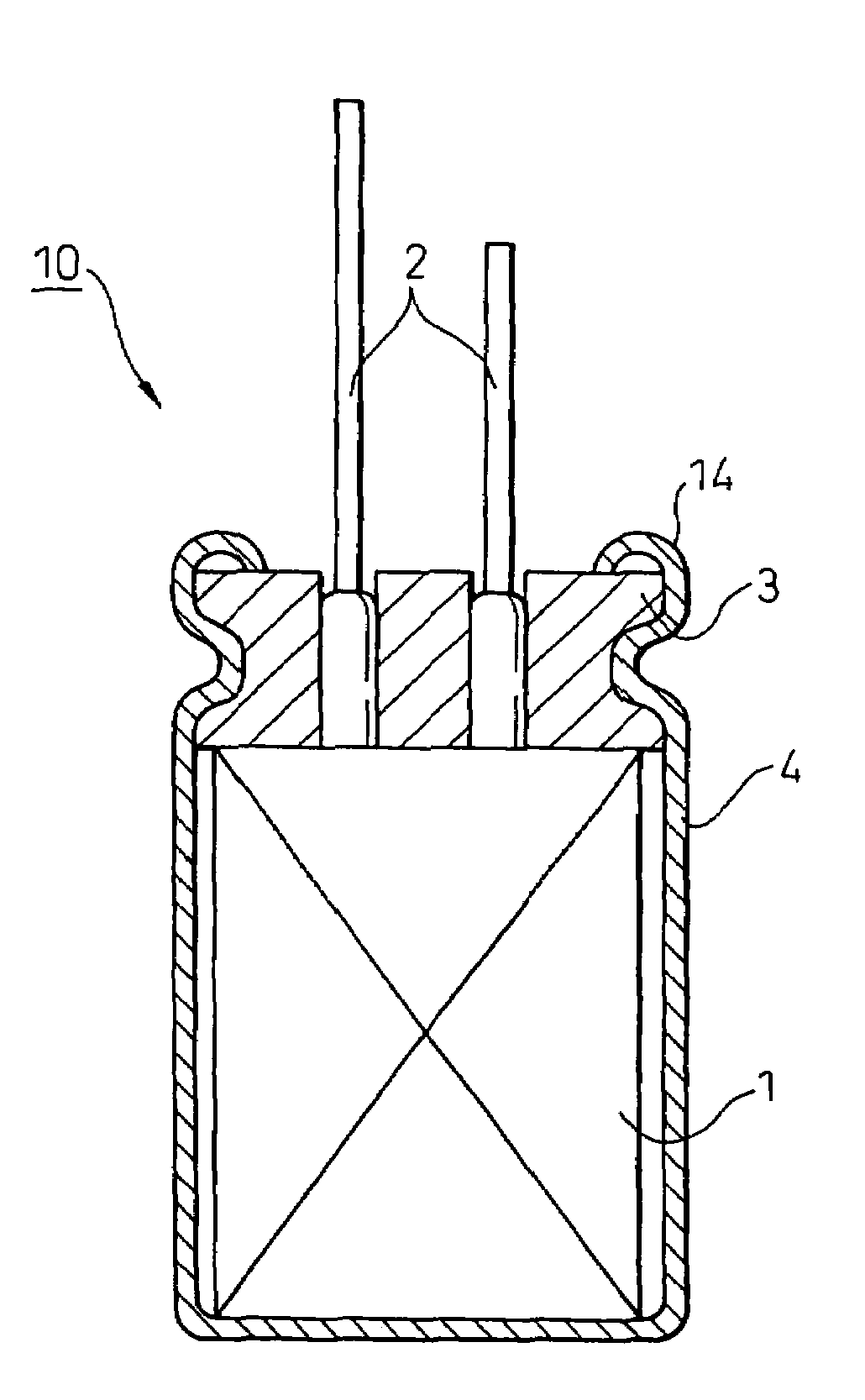
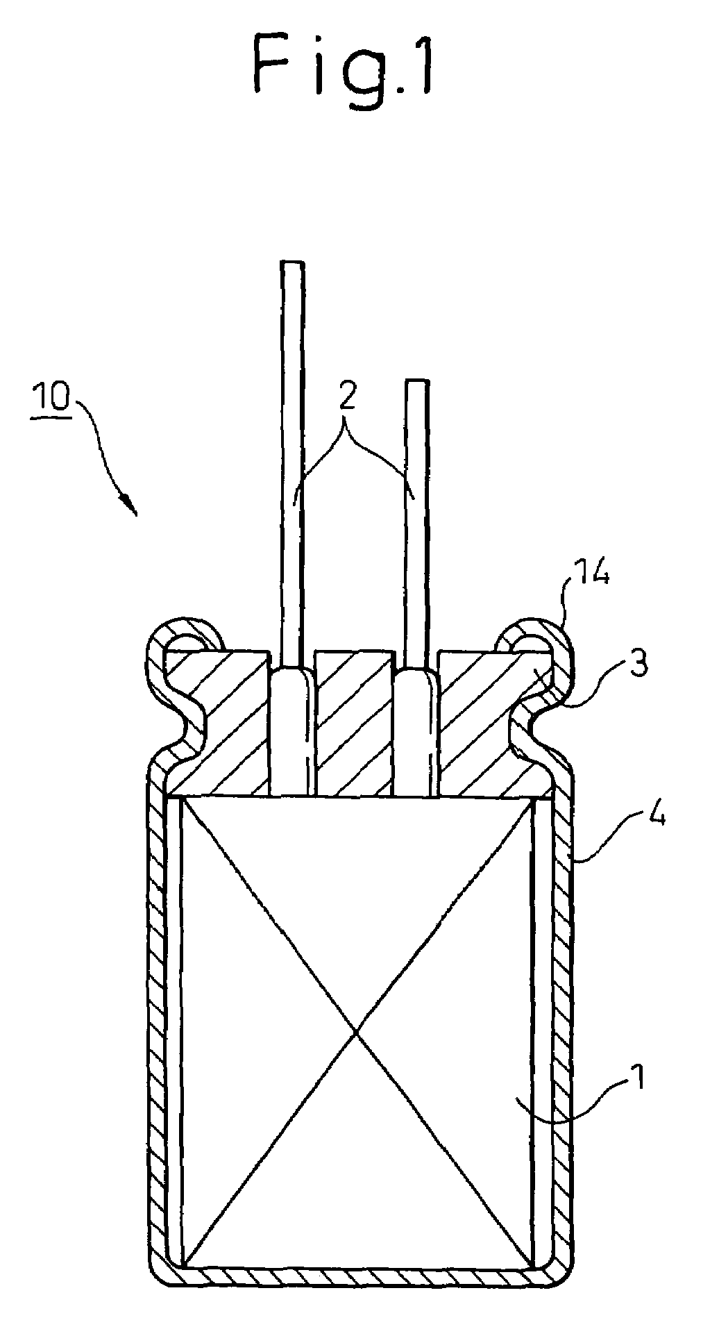
[0126]An aluminum electrolytic capacitor with a wound structure was produced in accordance with the following procedure.

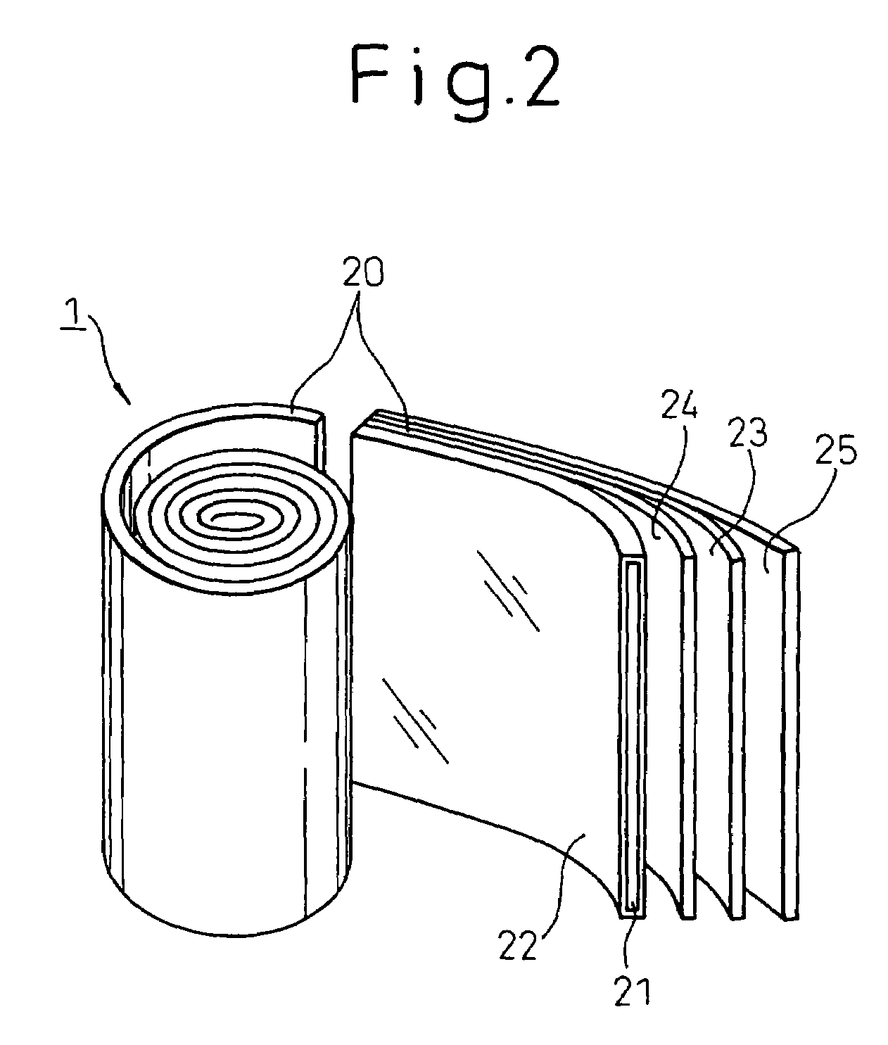
[0127]First, a high-purity aluminum foil was electrochemically etched to form an oxide film over the entire surface of the aluminum foil, and then a lead tab as an electrode was attached to make an aluminum anode foil. Regarding the lead tab used herein, the connection portion with the aluminum foil was made of an aluminum material and the external terminal was made of a copper material. Another aluminum foil was also electrochemically etched and the same lead tab as an electrode was attached to make an aluminum cathode foil. Subsequently, a capacitor element was made by interposing a separator made of natural fibers between the anode foil and the cathode foil, followed by winding.

[0128]The capacitor element was impregnated with an electrolyte solution whose compositions were shown in Table 1 below and contained in an aluminum case with a base so that the lead tab ...

examples 2 to 28

[0129]The same procedure as in Example 1 was repeated to obtain aluminum electrolytic capacitors, except that compositions of the electrolyte solution to be used were changed as described in Table 1 below in case of this example.


PUM

PropertyMeasurementUnit
densityaaaaaaaaaa
temperatureaaaaaaaaaa

Abstract

An electrolytic solution, for use in an electrolytic capacitor, comprising a solvent and a solute wherein water accounts for 20 to 100% by weight of the solvent and the total solute content is from 1.5 to 44% by weight, and an electrolytic capacitor comprising a capacitor element, a case containing the capacitor element, and a sealant with which the case is sealed, the capacitor element comprising a pair of electrode foils each comprising a dielectric, a separator for isolating the electrode foils from each other, and the above electrolytic solution filled between the electrode foils.

Description

TECHNICAL FIELD[0001]The present invention relates to an electrolytic solution for an electrolytic capacitor, and to an electrolytic capacitor using the same. More particularly, the present invention relates to an electrolytic solution, for use in an electrolytic capacitor, which has very low equivalent series resistance and shows an excellent temperature stability that has never been attained, and also shows excellent electrical characteristics under low temperature conditions and stable electrical characteristics at a temperature just above the freezing temperature, and to a high-performance electrolytic capacitor using the same. The electrolytic solution of the present invention is useful in an aluminum electrolytic capacitor and in other electrolytic capacitors.BACKGROUND ART[0002]Generally, a capacitor is a general electric part and has widely been used in power circuits and noise filters for digital circuits in various electric and electronic devices. Various electrolytic capa...

Claims


Application Information

Patent Timeline
Patent Type & Authority Patents(United States)
IPC IPC(8): H01G9/02H01M6/04H01G9/008H01G9/035H01G9/08H01G9/10H01G9/145
CPCH01G9/035H01G9/10H01G11/52H01G11/58H01G9/145Y02E60/13H01G9/022
Inventor UZAWA, SHIGERUKOMATSU, AKIHIKOOGAWARA, TETSUSHISAKURAI, YOSHISHIGE
Owner RUBYCON CORPORATION
Learn More