Impactor Automation

a technology of impactors and automation, applied in the field of impactor automation, can solve the problems of labor-intensive manual processes, and achieve the effect of facilitating the withdrawal of liquids

Inactive Publication Date: 2010-03-02
ASTECH PROJECTS
View PDF6 Cites 7 Cited by
  • Summary
  • Abstract
  • Description
  • Claims
  • Application Information

AI Technical Summary

Benefits of technology

[0016]In accordance with a second aspect of the present invention, there is a recovery device for recovering material collected upon working surfaces of components of a cascade impactor of the type comprising multiple impactor stages each comprising a respective stage body, the stage bodies being shaped to enable them to be assembled in a stack, locating one upon another, to form a conduit for through-flow of an aerosol sample, the stack having an axis, and the recovery device comprising multiple recovery stages separated vertically one from another and each adapted to receive a component from a respective impactor stage, each station comprising relatively movable upper and lower receptacle parts each shaped to receive the impactor component between themselves aid having peripheral sealing surfaces, the device further comprising a drive mechanism for moving the upper and lower parts apart, so that the impactor components are able to be introduced between them along a lateral direction, and for subsequently moving the upper and lower receptacle parts together, causing the peripheral sealing surfaces to seat upon each other or upon the impactor parts, so that each recovery stage forms a closed recovery chamber containing its impactor part, the recovery device further comprising conduits for circulating liquid through each of the recovery chambers.
[0027]The system allows for concurrent processing of multiple components, maximizing throughput.
[0035]To facilitate withdrawal of liquid from the closed loop, the reservoir has an inlet and an outlet, the inlet being higher than the outlet and being above a level to which the reservoir is filled, and the pumping device and / or associated valves being controllable to circulate the liquid around the closed loop in a forward direction for material collection and homogenization, the liquid passing into the reservoir through the inlet and out through the outlet, and in a reverse direction for discharge of the liquid, causing liquid to be withdrawn from the outlet without being drawn in through the inlet.

Problems solved by technology

The manual process is labour intensive.

Method used


Image

  • Impactor Automation
  • Impactor Automation
  • Impactor Automation

Examples


Embodiment Construction

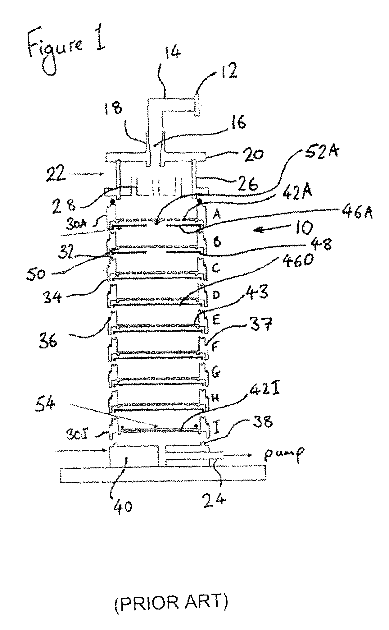
[0061]The cascade impactor 10 illustrated in FIG. 1 is of a well known and widely commercially available type known as an Andersen impactor. In use, a sample inhaler (omitted from this drawing) is presented to an elastomer (specifically rubber) mouthpiece 12 at the opening of a tubular throat 14, formed as an elbowed metal part with a frusto-conical taper 16 at its end remote from the mouthpiece, the taper forming a sealed friction fit in a complimentarily shaped inlet tube 18 of a lid 20 of a preseparator 22. Air is drawn through tire inhaler and tire impactor, via the throat, by means of a conduit 24 connected to a vacuum pump, which again is omitted from this drawing. The air passing through the impactor thus contains a dose of pharmaceutical from the inhaler.

[0062]The largest particles in the dose are typically bulking material such as lactose, and are collected in the preseparator 22. The preseparator comprises a cylindrical preseparator body 26 which receives the lid 20 and wi...


PUM

PropertyMeasurementUnit
rotationaaaaaaaaaa
distanceaaaaaaaaaa
displacementaaaaaaaaaa

Abstract

The application describes an automated system for carrying out tests using a cascade impactor 10 of the type having multiple impactor stages each comprising a respective stage body 30, the stage bodies being shaped to enable them to be assembled in a stack in which they locate one upon another. The system includes an expander device 90 having respective arms for supporting each of the stage bodies, and a mechanism for separating the arms along the axial direction to disassemble the impactor 10.

Description

CROSS-REFERENCE TO RELATED APPLICATIONS[0001]The present patent application claims priority from United Kingdom Patent Application No, 0616779.5, filed on Aug. 24, 2006.BACKGROUND OF THE INVENTION[0002]1). Field of the Invention[0003]The present invention is concerned with automation of tests carried out using a cascade impactor.[0004]2). Discussion of Related Art[0005]Cascade impactors are in themselves well known. They are used to analyze particle size distribution in aerosols. A particularly important application is in the testing of inhalers—devices used to dispense a controlled pharmaceutical dose into the mouth and lungs of a patient. Inhalers are used to treat asthma and other conditions. The pharmaceutical drug is typically in powdered or liquid form, much of its bulk being made up of a carrier and only a small percentage by the active ingredient. In use the patient releases a controlled dose of the powder or liquid using a mechanical arrangement such as a trigger lever. The...

Claims


Application Information

Patent Timeline
Patent Type & Authority Patents(United States)
IPC IPC(8): G01N1/22
CPCG01N15/0255G01N35/0099G01N1/2208G01N2015/0261
Inventor BRIDGE, MICHAEL JAMESHARVEY, DOMINIC EWANHANSFORD, CHRISTOPHER IAN
Owner ASTECH PROJECTS
Why Eureka
Try Eureka