Microfluidic systems with enhanced detection systems

a microfluidic and detection system technology, applied in the direction of fluid speed measurement, diaphragm, electrolysis, etc., can solve the problems of severely restricted sensitivity of capillaries, suffer from planar channel systems, and suffer from severe restricted sensitivity, so as to achieve enhanced sensitivity for optical detection

Active Publication Date: 2010-03-02
CAPLIPER LIFE SCI INC
View PDF54 Cites 127 Cited by
  • Summary
  • Abstract
  • Description
  • Claims
  • Application Information

AI Technical Summary

Benefits of technology

[0006]The present invention generally provides systems and methods for performing analytical operations in mi

Problems solved by technology

Despite these advantages, these planar channel systems suffer from a problem that is common to conventional capillary analytical systems.
In particular, capillary systems, because of their extremely small volumes, can suffer from severely restricted sensitivity due to the simple lack of detectable amounts of material.
This results in only the small amount of material that is present at the detection spot being subjected to the detection operation at any given time.
In many interesting analytical reactions, such labels are not readily av

Method used


Image

  • Microfluidic systems with enhanced detection systems
  • Microfluidic systems with enhanced detection systems
  • Microfluidic systems with enhanced detection systems

Examples


example 1

Efficacy of Orthogonally Oriented Detection Channel Segment

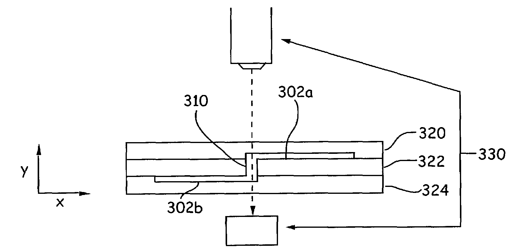
[0054]A microfluidic system employing an absorbance detection scheme was assembled employing the detector shown in FIG. 4. In addition, the system employed a simple microfluidic device having the structure illustrated in FIGS. 5A and 5B. In particular, the device 500 was fabricated as an aggregate of three substrate layers 502, 504 and 506, where channel 508a was fabricated between substrates 502 and 504 while channel 508b was fabricated between substrates 504 and 506. The two channels were connected by a via 510 fabricated through substrate layer 504, that forms the detection channel segment. The via or detection channel segment 510 was disposed through the entire center substrate that had a nominal thickness of 700 μm. When added to the depth of the channels on either end, this yielded a detection path length of approximately 720 μm Channel 508a terminated at one end at reservoir 512, and at the other at via 510, while cha...


PUM

PropertyMeasurementUnit
Flow rateaaaaaaaaaa
Diameteraaaaaaaaaa

Abstract

Microfluidic devices and systems having enhanced detection sensitivity, particularly for use in non-fluorogenic detection methods, e.g., absorbance. The systems typically employ planar microfluidic devices that include one or more channel networks that are parallel to the major plane of the device, e.g., the predominant plane of the planar structure, and a detection channel segment that is substantially orthogonal to that plane. The detection system is directed along the length of the detection channel segment using a detection orientation that is consistent with conventional microfluidic systems.

Description

CROSS-REFERENCE TO RELATED APPLICATIONS[0001]This application is a continuation in part of U.S. Ser. No. 10 / 076,136, filed Feb. 14, 2002, which claims priority to U.S. Ser. No. 60 / 269,174, filed Feb. 15, 2001, each of which is incorporated herein in its entirety for all purposes.BACKGROUND OF THE INVENTION[0002]Microfluidic devices and systems have been developed that give researchers substantial advantages in terms of the miniaturization, automation and integration of a large number of different types of analytical operations. For example, continuous flow microfluidic devices have been developed that perform serial assays on extremely large numbers of different chemical compounds, e.g., for use in high-throughput pharmaceutical screening operations (see, e.g., U.S. Pat. Nos. 5,942,443 and 6,046,056). Other microfluidic devices have been developed that perform rapid molecular separations on a number of different samples in relatively short time frames (see, U.S. Pat. No. 5,976,336)....

Claims


Application Information

Patent Timeline
IPC IPC(8): G01N33/48B01L3/00B81B1/00G01N21/05
CPCB01L3/502715G01N21/05B01L2300/0654B01L2300/0816B01L2300/0861B01L2300/0874Y10T436/2575B01L2400/0415B01L2400/0487B01L2400/084G01N2021/0346B01L2300/0887
Inventor CHIEN, RING-LINGWOLK, JEFFREY A.SPAID, MICHAELMCREYNOLDS, RICHARD J.
Owner CAPLIPER LIFE SCI INC
Why Eureka
Try Eureka