Flow measurement in partially filled pipes using pulsed peak velocity doppler

a technology of flow velocity and doppler, which is applied in the direction of fluid pressure measurement by mechanical elements, volume flow measurement devices, special data processing applications, etc., can solve the problems of system difficulty, inability to accurately measure the average velocity, and inability to screen the distance of particles by closer particles, etc., to achieve accurate and economic measurement of flow velocity

Active Publication Date: 2010-03-02
ADS
View PDF22 Cites 17 Cited by
  • Summary
  • Abstract
  • Description
  • Claims
  • Application Information

AI Technical Summary

Benefits of technology

[0019]By transmitting pulses and then sampling the return signal when the transmitter is off, the impact of transmit signal coupling can be effectively ignored. This effectively increases the dynamic range of the system, allows the sensing of weaker signals and facilitates distinguishing between signal and noise. It allows operation without variable gain amplifiers and without a carrier notch filter. This simplifies system design, reduces cost, reduces noise, allows flows of as low as 0.1 ft / s (3 cm / sec) to be readily measured, and makes the determination of velocity direction more robust. Because this technique does not rely on the measurement of velocities in specific flow volumes or cells, it is suitable for monitoring flows in pipes that have as little as 1 inch (2.5 cm) or less depth.

Problems solved by technology

However the average velocity is difficult to measure because the flow velocity through the cross-section of flow varies greatly.
In sewers, such systems may have difficulty either if the sensor is placed too close to the edge (where all flows are zero) or may foul if placed to deep into the flow.
A distinct issue with such systems is that they interpret signal strength as a measure of velocity and then weight these numbers to provide an average velocity.
Other parasitic effects such as surface reflections, screening of distant particles by closer particles can also be a source of error.
One significant limitation of such CW systems is that the received signal (generally very weak) must be sensed in the presence of the continuous and very strong transmitted signal.
Not only does this make the measurement of very weak distant signals difficult, but it also makes it difficult to measure very slow flows.
Similarly, this makes it more difficult to distinguish between slow negative and slow positive flow.
This problem is compounded if the sensor becomes fouled.
In such cases, the coupling from transmit to receive can increase thus increasing useless crosstalk and while attenuating the signal received from distant particles.
Useful information (music) is attenuated and the increased coupling by the pillow makes it more difficult to distinguish the scream from the music.
Such devices are known to work well in large pipes and deep flows but tend to be expensive and also have limited functionality if the flow is too shallow (i.e less than a few centimeters).

Method used


Image

  • Flow measurement in partially filled pipes using pulsed peak velocity doppler
  • Flow measurement in partially filled pipes using pulsed peak velocity doppler
  • Flow measurement in partially filled pipes using pulsed peak velocity doppler

Examples


Embodiment Construction

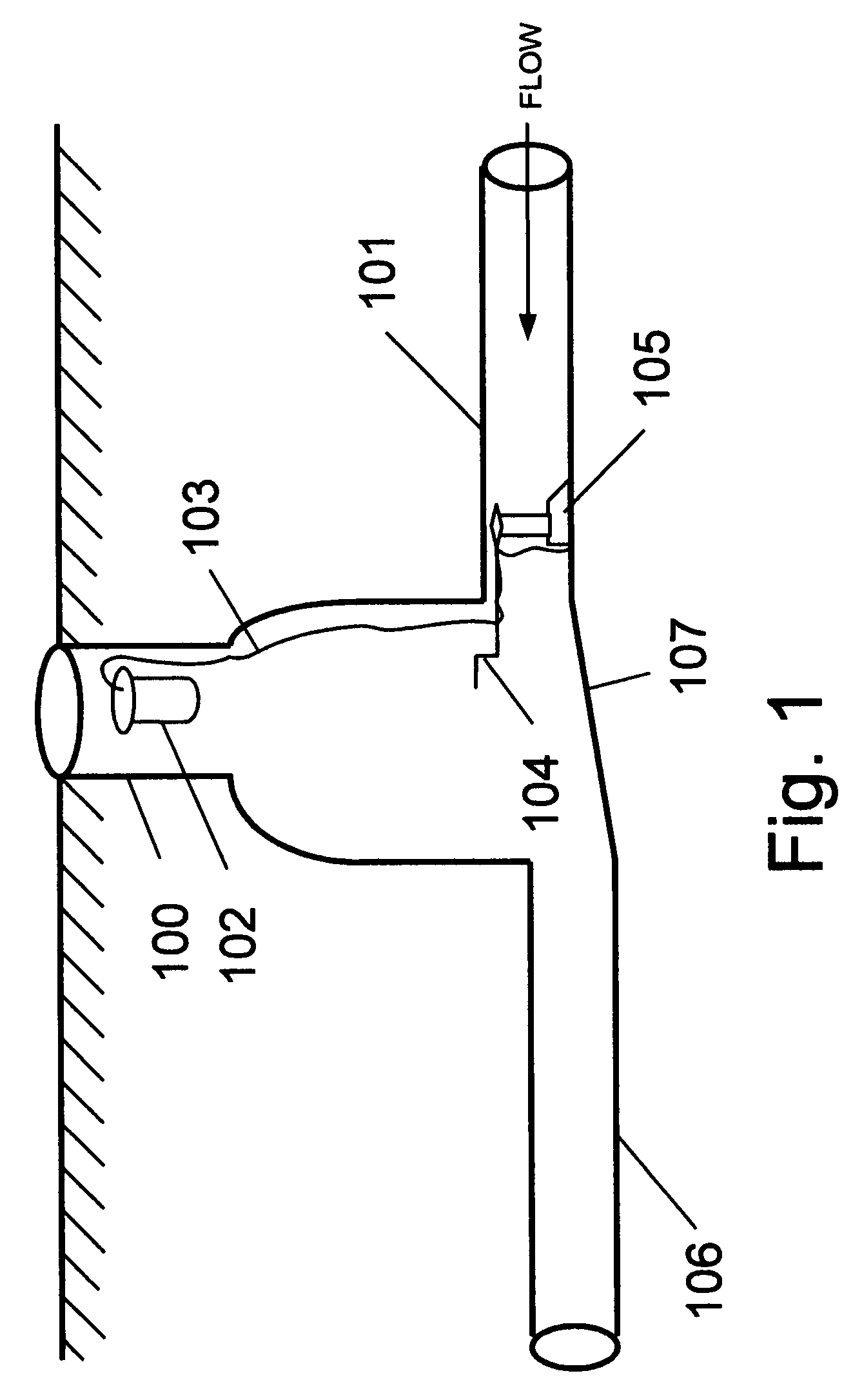
[0032]Turning, now, specifically to FIG. 1, a transmitting and receiving ultrasonic sensor 105 is mounted on an expandable scissors jack mounting ring 104 and is installed in the influent pipe 101 of manhole 100. The scissors jack mounting, as described in Petroff U.S. Pat. No. 4,116,061, is ideal for installation in smaller diameter pipes. U.S. Pat. No. 4,116,061, titled “Sewer Line Analyzer Probe,” issued Sep. 26, 1978 to Petroff is hereby incorporated herein by reference. In the arrangement of FIG. 1, the sensor is preferably positioned at the bottom of the pipe such that it is “looking” up stream. If silt, rock or other debris is present, then the sensor and ring can be installed such that the ring is in contact with the pipe wall (and beneath the debris) but the sensor is located above the debris on the side of the pipe. In all cases, the sensor should be installed below the surface of the water, or in the case of a normally dry pipe, at a point in the pipe where the flow is ex...


PUM


Abstract

The present invention relates to a system and method for measurement of flow velocity using the transmission of a sequence of coherent pulsed ultrasonic signals into the flow, and sampling the received response signal at a predetermined delay time relative to the pulse transmission that does not correspond to the signal transmission time. The sampling may be coherent with a frequency offset from the coherency frequency of the pulses. The received signal samples are then spectrally processed, typically by a Fourier process, to generate a frequency domain data set. A threshold technique is used on the frequency domain data set to determine a peak Doppler shift. Average velocity is then obtained by multiplying the peak Doppler shift by a factor, for example, 0.90. In one embodiment, the transmit pulse and receive samples are interleaved by alternating between transmitting a pulse and, after a delay, sampling the received signal.

Description

RELATED APPLICATIONS[0001]This application is an application claiming the benefit under 35 USC 119(e) of prior U.S. Provisional Application 60 / 832,183, titled “Hydraulic Flow Monitoring System”, filed Jul. 20, 2006 by Petroff, which is hereby incorporated herein by reference in its entirety.BACKGROUND[0002]1. Field of the Invention[0003]The present invention pertains generally to the field of measurement of water flowing in partially and completely full pipes using a sensor that is in contact with the flow, more particularly, to the class of devices that utilize ultrasonic energy and measurement of the Doppler Effect as a means to determine the channel velocity.[0004]2. Background of the Invention[0005]There are many cases where it is important to measure the rate of flow in a pipe. For example, one may need to know the flow rate to determine a billing rate between two communities, to assess the rate at which rain or ground water is entering the sewage system, to design a system exp...

Claims


Application Information

Patent Timeline
Patent Type & Authority Patents(United States)
IPC IPC(8): G01F1/00G01F17/00G01F23/00G01P11/00G01S13/00G01S15/00
CPCG01F1/663G01F1/667H04L67/34
Inventor PETROFF, ALAN M.
Owner ADS
Why Eureka
Try Eureka