
Battery pack

a battery pack and battery technology, applied in secondary cell servicing/maintenance, instruments, transportation and packaging, etc., can solve the problems of large circuit size of analog-to-digital converter, difficult to install the detector in a small battery pack, and difficulty in detecting a remaining battery charge by its voltag

Active Publication Date: 2010-03-09
MITSUMI ELECTRIC CO LTD
View PDF14 Cites 15 Cited by
  • Summary
  • Abstract
  • Description
  • Claims
  • Application Information

AI Technical Summary

Benefits of technology

The present invention provides a small-sized battery pack that can detect the remaining battery charge. The battery pack includes a current detecting unit, a modulating unit, a memory, and a CPU. The current detecting unit detects the charging and discharging currents of the battery and outputs an analog signal. The modulating unit modulates the analog signal to a PDM (pulse density modulation) signal. The memory stores a conversion program for converting the PDM signal into PCM (pulse code modulation) data and a remaining battery charge calculating program for calculating the remaining battery charge by accumulating the PCM data. The CPU converts the PDM signal into the PCM data and calculates the remaining battery charge by executing the remaining battery charge calculating program. The battery pack also includes a voltage detecting unit, a temperature detecting unit, and a selecting unit. The remaining battery charge calculating program corrects the remaining battery charge by using the PCM data of the voltage and temperature detected by the voltage and temperature detecting units. The modulating unit is a sigma-delta modulator. The current detecting unit, modulating unit, memory, and CPU are integrated into one semiconductor integrated circuit. The technical effect of the invention is to provide a small-sized battery pack with a remaining battery charge detection function.

Problems solved by technology

In the lithium-ion battery, generally, it may be difficult to detect a remaining battery charge by its voltage.
However, the circuit size of an analog-to-digital converter is large; therefore, it is difficult to install the detector in a small sized battery pack.

Method used


Image

  • Battery pack
  • Battery pack
  • Battery pack

Examples


first embodiment

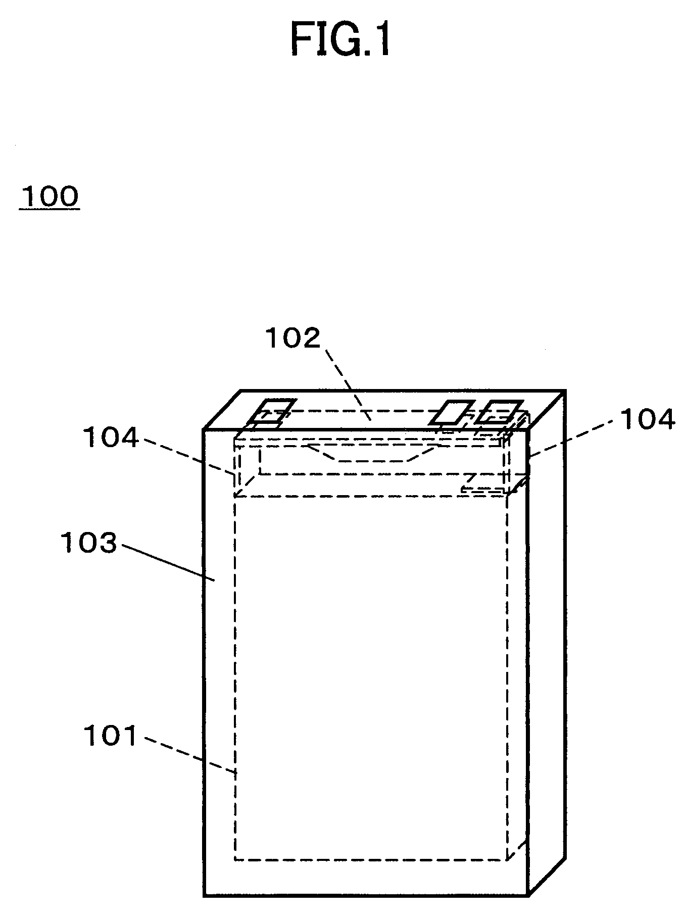
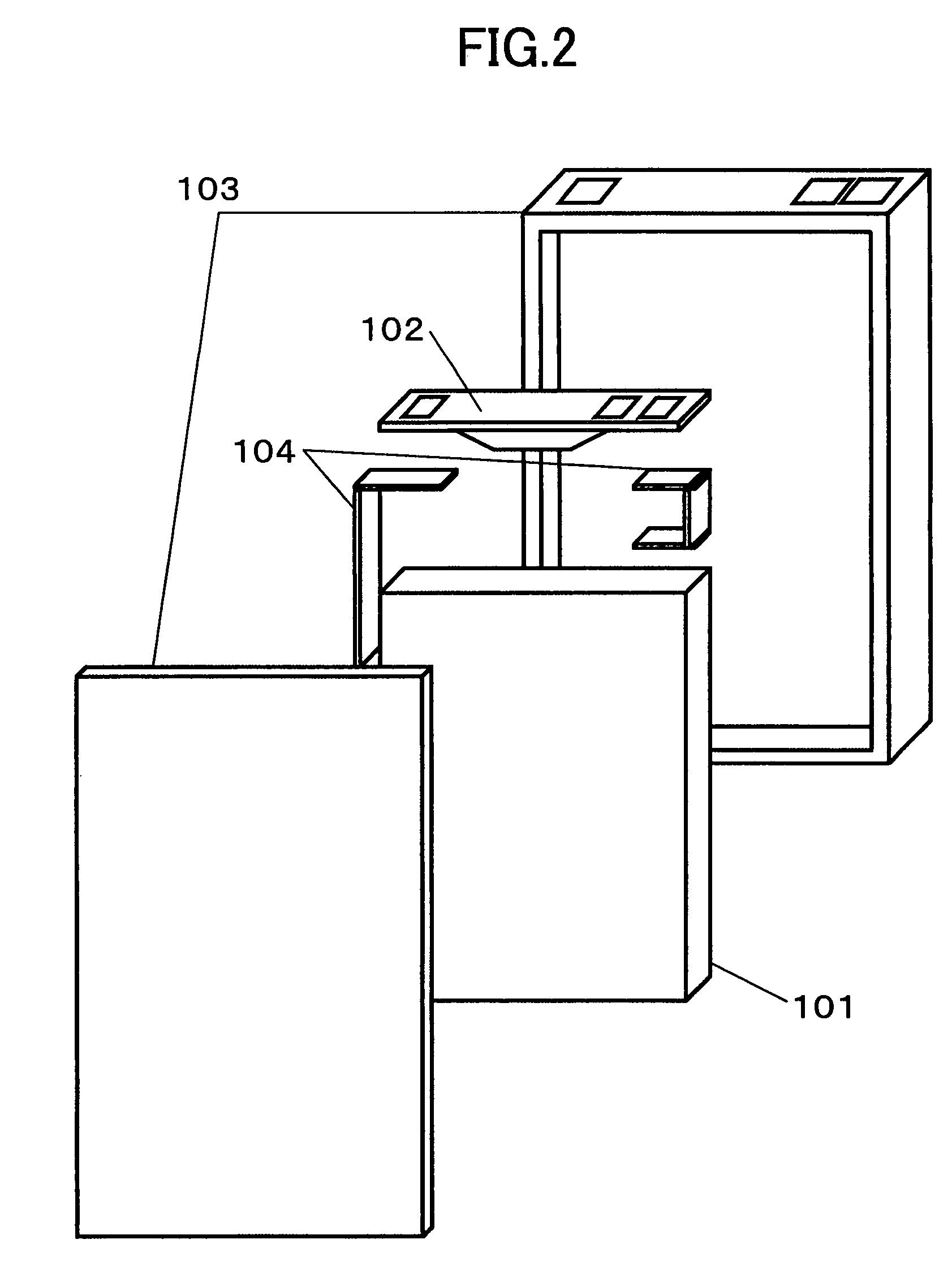
[0032]FIG. 1 is a perspective view of a battery pack according to a first embodiment of the present invention. FIG. 2 is an exploded perspective view of the battery pack shown in FIG. 1.

[0033]As shown in FIGS. 1 and 2, in a battery pack 100, a battery 101 and a circuit board 102 are contained in a case 103. The battery 101 is, for example, a lithium-ion battery and is connected to the circuit board 102 via connecting terminals 104.

[0034]FIG. 3 is a perspective view of the circuit board 102. As shown in FIG. 3, in the circuit board 102, a fuel gauge IC 111, a regulator / protection circuit 112, a transistor 113, and a current detecting resistor Rs (refer to FIG. 4) are mounted on a printed circuit board 114 having a two-layer or a multi-layer structure.

[0035]The fuel gauge IC 111 detects the remaining battery charge of the battery 101 by accumulating charging and discharging currents of the battery 101. The remaining battery charge detected by the fuel gauge IC 111 is output to an exte...

second embodiment

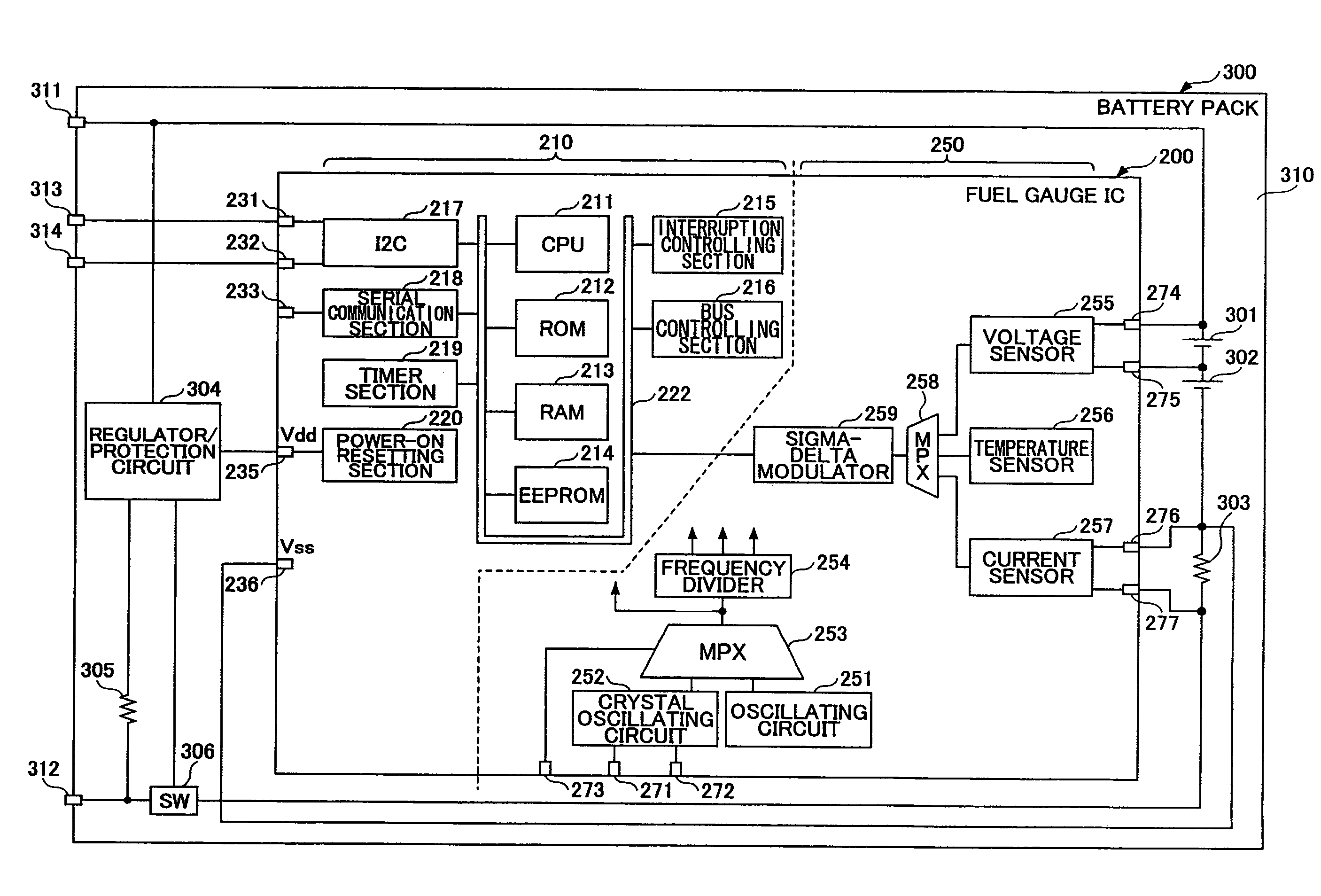
[0082]FIG. 11 is a block diagram showing a battery pack according to a second embodiment of the present invention. As shown in FIG. 11, a fuel gauge IC 200 includes a digital section 210 and an analog section 250.

[0083]The digital section 210 includes a CPU 211, a ROM 212, a RAM 213, an EEPROM 214, an interruption controlling section 215, a bus controlling section 216, an I2C section 217, a serial communication section 218, a timer section 219, and a power-on resetting section 220. The above elements (sections) are connected with each other via an internal bus 222.

[0084]The CPU 211 controls all the elements in the fuel gauge IC 200 by executing programs stored in the ROM 212. With this control, the CPU 211 calculates the remaining battery charge by accumulating charging and discharging currents of a battery. At this time, the RAM 213 is used as working storage. In the EEPROM 214, trimming information and so on are stored. In FIG. 11, the CPU 211 corresponds to the CPU 123 shown in F...


PUM


Abstract

A battery pack is disclosed. The battery pack includes a battery; a current detecting unit which detects charging and discharging currents of the battery and outputs an analog signal corresponding to the charging and discharging currents; a modulating unit which modulates the analog signal to be a PDM (pulse density modulation) signal by applying a PDM modulation to the analog signal; a memory in which a conversion program for converting the PDM signal into PCM (pulse code modulation) data and a remaining battery charge calculating program for calculating a remaining battery charge by accumulating the PCM data are stored; and a CPU, which converts the PDM signal into the PCM data which are digital data by being supplied the PDM signal from the modulating unit while executing the conversion program stored in the memory, and calculates the remaining battery charge by accumulating the PCM data while executing the remaining battery charge calculating program stored in the memory.

Description

BACKGROUND OF THE INVENTION[0001]1. Field of the Invention[0002]The present invention relates to a battery pack which measures a remaining battery charge.[0003]2. Description of the Related Art[0004]Recently, lithium-ion batteries have been loaded in mobile devices, for example, a digital still camera. In the lithium-ion battery, generally, it may be difficult to detect a remaining battery charge by its voltage. In order to detect the remaining battery charge of the battery, there is a method in which charging and discharging currents in the battery are accumulated (refer to Patent Document 1).[0005]Since a current is consumed even if the lithium-ion battery is detached from the mobile device, a user needs a detector that detects the remaining battery charge by accumulating the charging and discharging currents of the lithium-ion battery, a regulator / protection circuit, and so on which are contained in a case as a battery pack.[0006]In the detector, analog signals such as current va...

Claims


Application Information

Patent Timeline
Patent Type & Authority Patents(United States)
IPC IPC(8): H02J7/00
CPCH01M10/44Y02E60/10
Inventor NAKANO, ITSUKIIKEUCHI, AKIRA
Owner MITSUMI ELECTRIC CO LTD
Learn More