Combustion plume absorption gauge

Inactive Publication Date: 2010-03-09
THE UNITED STATES OF AMERICA AS REPRESENTED BY THE SECRETARY OF THE NAVY
View PDF29 Cites 6 Cited by
  • Summary
  • Abstract
  • Description
  • Claims
  • Application Information

AI Technical Summary

Benefits of technology

[0010]Each gauge has a generally elongated shape and at least a portion of the elongated shape utilizes the pencil form, having a tapered or conical shape. When placed a known distance from the explosive charge, the pencil form of each leg is positioned to point towards the charge to minimize the turbulence that is added to the combustion environment by the presence of the gauge itself. The two portions of the gauge, forming two separate or independent halves

Problems solved by technology

In general, however, absorption spectroscopy systems are not constructed for use in hazardous environments where the systems or probes would experience elevated temperatures and pressures.
The arrangement of the probe makes it suitable for pressures up to 2000 psi and temperatures up to 600° F. However, the probe is isolated from the hazardous environment and requires sturdy structures to pro

Method used


Image

  • Combustion plume absorption gauge
  • Combustion plume absorption gauge

Examples


Embodiment Construction

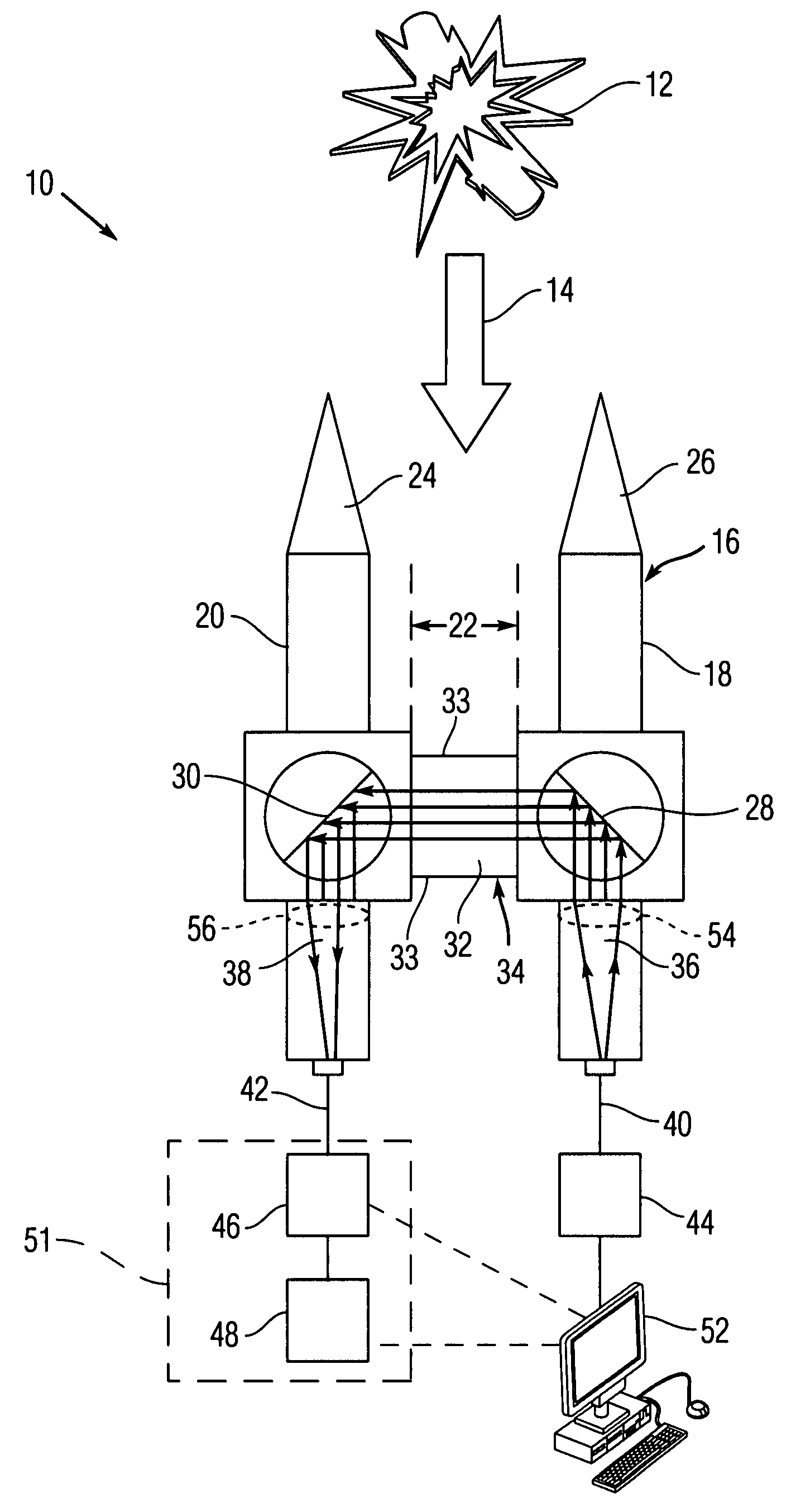
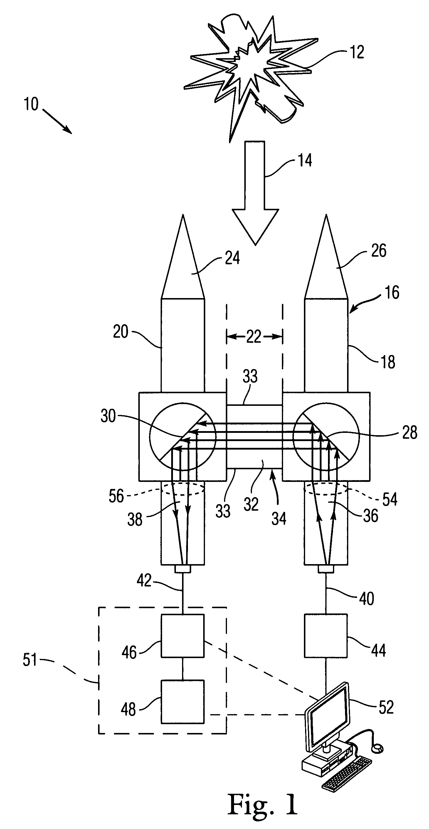
[0013]Referring to FIG. 1, an exemplary embodiment of a system 10 for measuring atomic and molecular decomposition products of an explosive event utilizing an absorption spectroscopy gauge 16 in accordance with the present invention is illustrated. The system 10 includes at least one absorption spectroscopy gauge 16 in communication with a light source 44 and a time-resolved spectroscopy system 51. The time-resolved spectroscopy system 51 includes a spectrometer 46 to produce a wavelength dispersion of the incoming light across the wavelengths of interest. The spectrometer is in communication with, and delivers the wavelength-dispersed light to, time-resolved detector such as a camera or array 48. If very fast time-scales are probed (for example, having a sub-microsecond time resolution), the camera can be a streak unit to amplify and to disperse the light temporally. Therefore, the time-resolved spectroscopy system51 can produce a time-resolved profile of the non-absorbed light pas...


PUM


Abstract

An absorption spectroscopy gauge to measure chemical concentrations in a post-detonation combustion cloud of energetic materials. A broadband light source coupled to an optical fiber guides light into a gauge via a first leg where a plano-convex lens collimates the light source internally. The light reflects off a mirror and passes through an absorption region before entering a second leg of the gauge where it is refocused into a different fiber and sent to a time-resolved spectroscopy system for analysis. The time-resolved spectroscopy system can include a spectrometer and a steak camera. The two legs of the gauge are arranged as separate halves connected by a plurality of rods that can be adjusted to change the length of the absorption region. The gauge is arranged to include stainless steel cone shaped tips to minimize added turbulence brought upon by its use.

Description

STATEMENT OF GOVERNMENT INTEREST[0001]The invention described herein may be manufactured and used by or for the Government of the United States of America for Governmental purposes without the payment of any royalties thereon or therefore.FIELD OF THE INVENTION[0002]The present invention is directed to time-resolved absorption spectroscopy.BACKGROUND OF THE INVENTION[0003]Spectroscopic analysis provides information about the identity, structure, and concentration of the chemical species of a given sample using the detected energy change of an atom or molecule through either the emission or absorption of a photon. Absorption spectroscopy measures the net absorption of incident radiation throughout a chosen wavelength range. Radiation passing through a sample is attenuated depending upon the path length traveled by the radiation, the strength and concentration of absorbing species present and scattering losses. Unique spectral fingerprints arise from the absorption of photons of light...

Claims


Application Information

Patent Timeline
IPC IPC(8): G01J3/42
CPCG01J3/02G01J3/021G01J3/42G01N21/255G01N2021/1793
Inventor CARNEY, JOEL R.WILINSON, JOHN
Owner THE UNITED STATES OF AMERICA AS REPRESENTED BY THE SECRETARY OF THE NAVY
Why Eureka
Try Eureka