
Power and signal distribution system for use in interior building spaces

a power and signal distribution system and interior building technology, applied in relays, emergency protective arrangements for limiting excess voltage/current, transportation and packaging, etc., can solve the problems putting significant limitations on the total power available for devices, and reducing the efficiency of the device, so as to preserve mechanical functionality and general installation characteristics, the effect of reducing the overall consumption of electrical energy

Inactive Publication Date: 2010-03-16
WORTHINGTON ARMSTRONG VENTURE
View PDF40 Cites 16 Cited by
  • Summary
  • Abstract
  • Description
  • Claims
  • Application Information

AI Technical Summary

Benefits of technology

"The invention is a power and signal distribution system for building interior spaces that optimizes power efficiency through load grouping and active power and signaling transmission routing. The system includes a mesh-like structure with conductive elements connected by shunt switches. The shunt switches provide a configurable point for the system, allowing for passive or active routing of power and signals. The system can reconfigure itself to utilize multiple paths and reduce energy consumption while maintaining mechanical functionality. It also allows for both local and central control of the active power grid."

Problems solved by technology

A challenge of the primary power distribution infrastructure in modern commercial buildings is the need for conversion of power from high voltage, generally 110-230 volts AC, to low voltage, generally 3-24 volts DC.
Therefore, improving the raw electricity consumption efficiency of conventional AC / DC transformers has the potential to dramatically reduce energy costs.
Unfortunately, conventional low cost AC / DC transformers are designed to maximize their efficiency given a specific expected load or range of loads, thus producing efficiencies which are statistically highly variable.
In this regard, the NEC puts significant limitation on the total power available for devices attached to any one conductive segment as described therein.
Such load management, including real-time monitoring, is not sufficiently accommodated in current LVDC power distribution systems.

Method used


Image

  • Power and signal distribution system for use in interior building spaces
  • Power and signal distribution system for use in interior building spaces
  • Power and signal distribution system for use in interior building spaces

Examples


Embodiment Construction

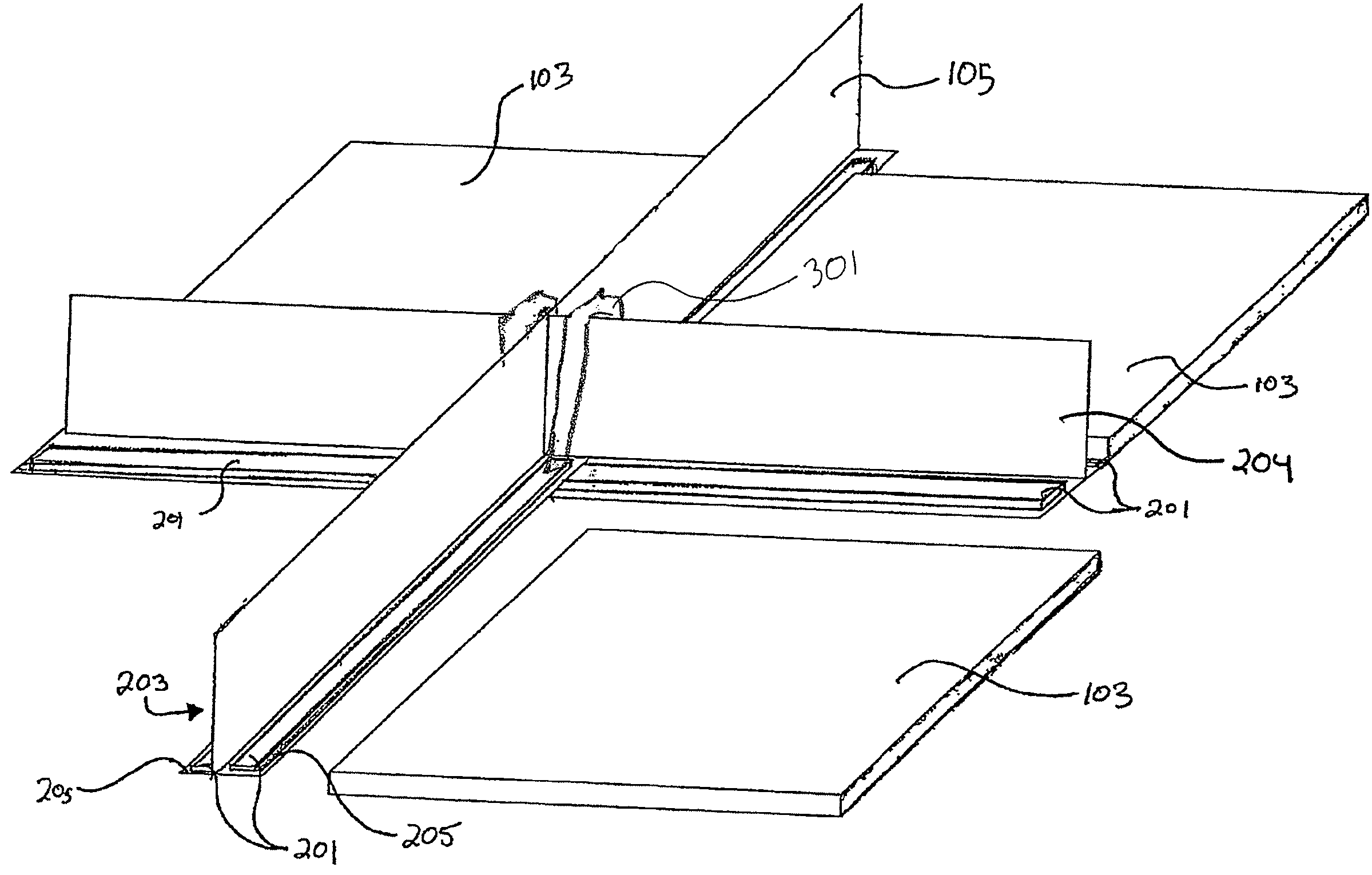
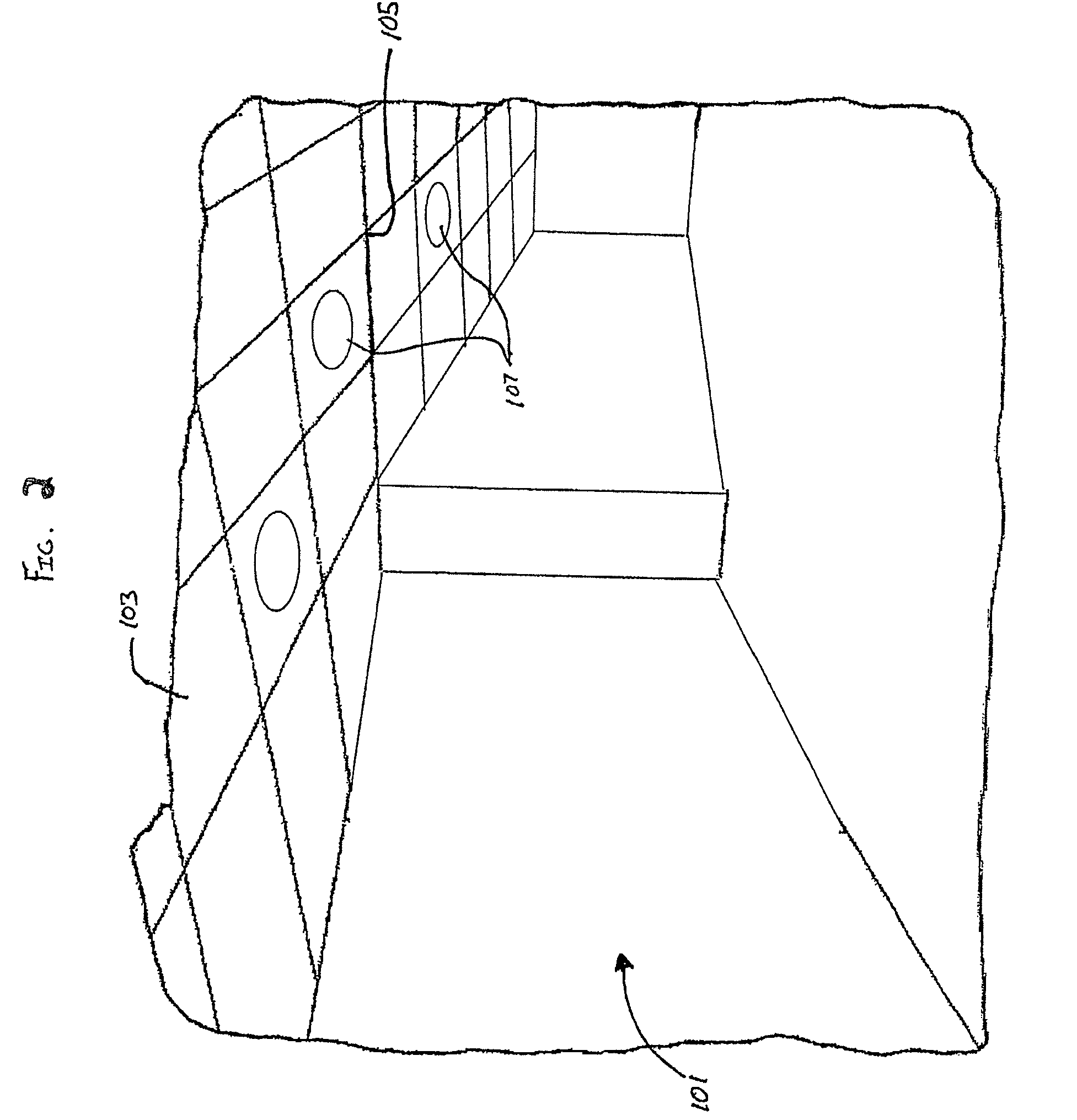
[0024]The present invention includes a system for distributing power and or signals within an electrified ceiling framework system. In particular, the present invention includes a framework, preferably mounted onto the structural overhead of a room space 101, that is capable of providing power to low voltage electrical devices 107. FIG. 2 shows a room space 101 having a ceiling 103 supported by a ceiling grid framework 105. The framework 105 is arranged to allow connections of conductive elements on or within the framework 105 to provide selective power distribution and / or selective signal distribution. For example, power for the electrical devices 107 is provided by conductive elements or conductors 201 (see FIG. 3) placed upon surfaces of the ceiling grid framework 105. The ceiling 103 may include decorative tiles, acoustical tiles, insulative tiles, lights, heating ventilation and air conditioning (HVAC) vents, other ceiling elements or covers and combinations thereof. Electrical...


PUM


Abstract

A power and signal distribution system for the building interior and a method for operating a power and signal distribution system for the building interior are provided. The system includes a plurality of conductors adjacent to at least one surface of a plurality of support members forming a grid. The system further includes at least one shunt switch in communication with at least two conductors, the shunt switch being configurable to selectively conduct power or signals between the at least two conductors.

Description

FIELD OF THE INVENTION[0001]The present invention is directed to a self-configuring power mesh and in particular, to a grid system which utilizes the concept of a self-configuring power mesh to distribute power and signaling in the interior of a building.BACKGROUND OF THE INVENTION[0002]The electrical grid connecting America's power plants, transmission lines and substations to homes, businesses, and factories operates almost entirely within the realm of high voltage alternating current (AC). Yet an increasing fraction of devices found in those buildings actually operate on low voltage direct current (DC). These devices include, but are not limited to, digital displays, remote controls, touch-sensitive controls, transmitters, receivers, timers, light emitting diodes (LEDs), audio amplifiers, microprocessors, and virtually all products utilizing rechargeable batteries. A challenge of the primary power distribution infrastructure in modern commercial buildings is the need for conversi...

Claims


Application Information

Patent Timeline
Patent Type & Authority Patents(United States)
IPC IPC(8): H01H47/00E04C2/52H02G3/30H02G3/22H02B1/01H02G3/08H01H35/00
CPCH02G3/00H02G3/281H02G3/381Y04S40/121H02J13/002Y02B90/2615H02J13/00007Y02B90/20
Inventor PATTERSON, BRIAN T.BROWNE, SEAN D.BEAKES, WILLIAM E.FRECSKA, SANDOR A.MYERS, JERE W.
Owner WORTHINGTON ARMSTRONG VENTURE
Learn More