
High speed clock distribution transmission line network

a transmission line network and high-speed clock technology, applied in the field of vlsi, can solve the problems of consuming a significant portion of the clock period, skew can be a limiting factor, and the design of a robust global clock distribution system which can sustain various parameter variations becomes increasingly difficult and time-consuming

Active Publication Date: 2010-03-16
RGT UNIV OF CALIFORNIA
View PDF10 Cites 8 Cited by
  • Summary
  • Abstract
  • Description
  • Claims
  • Application Information

AI Technical Summary

Benefits of technology

[0019]Clock distribution methods and circuits in accordance with preferred embodiments of the invention can provide several advantages. There is no direct feedback path from the transmission line network to the clock source. The transmission lines are a linear network, and thus the design and optimization involve no active components. Another advantage is that the energy storage capability of the locked standing wave in the transmission line can mitigate the clock jitter. Additionally, power consumption the network is low as a result of the resonance effect of the transmission line.

Problems solved by technology

As clock frequencies increase, the skew can be a limiting factor.
With increasing clock frequency, the clock skew caused by many nondeterministic factors such as process variations, supply voltage fluctuation and temperature gradient consumes a significant portion of clock period.
For high performance synchronous circuitry, the design of a robust global clock distribution system which can sustain various parameter variations becomes an increasingly difficult and time-consuming task.
However, the trend is toward higher clock frequencies at which the inductance effect can no longer be ignored.
The RC model of the shunt effect is not valid at such frequencies.
The inductance of the shunt can even cause worse skew.
However, the distribution scheme of O'Mahony et al. does not use a global clock source.
Compared to a passive scheme, though, the active component approach raises stability issues and, in some cases, may be more sensitive to process variations during fabrication.

Method used


Image

  • High speed clock distribution transmission line network
  • High speed clock distribution transmission line network
  • High speed clock distribution transmission line network

Examples


Embodiment Construction

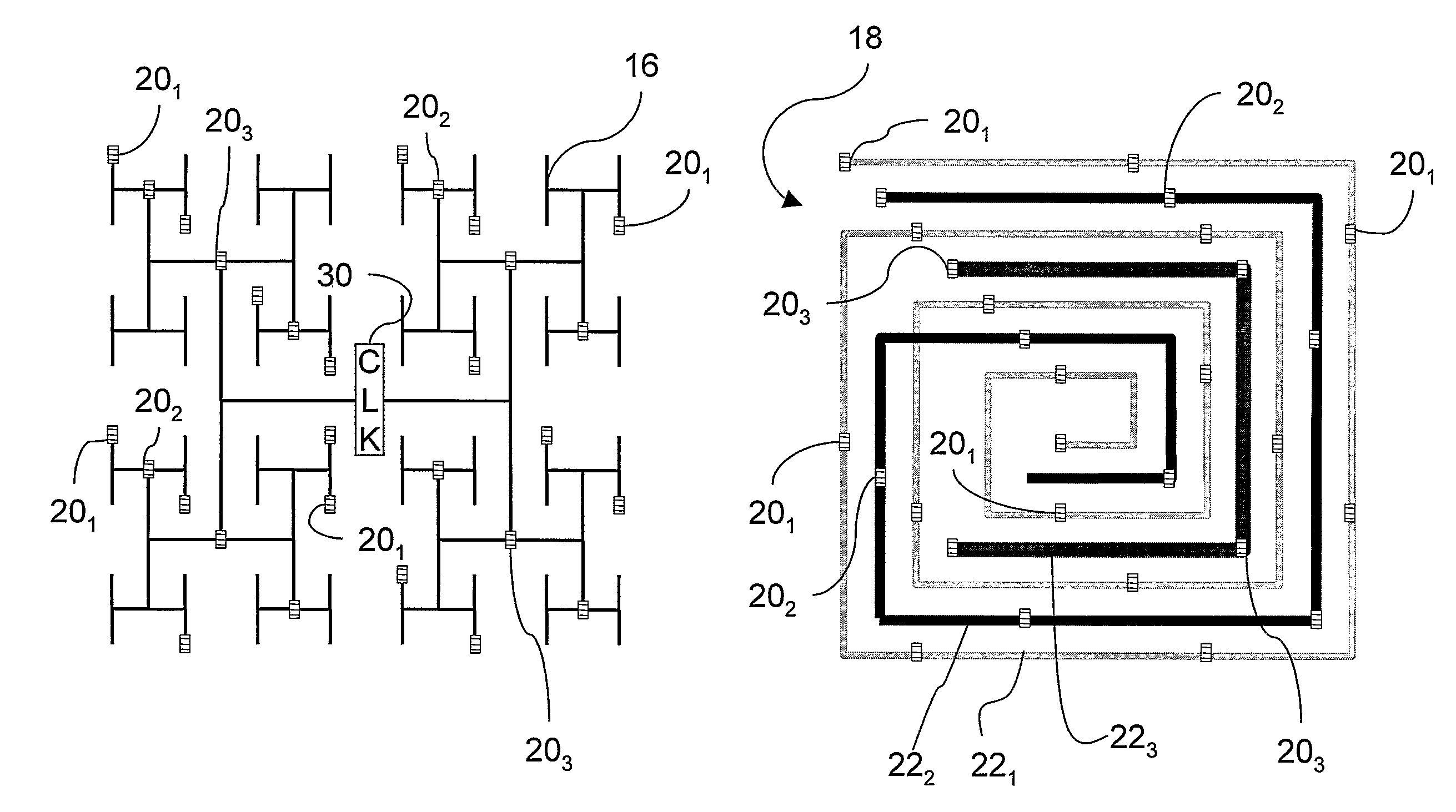
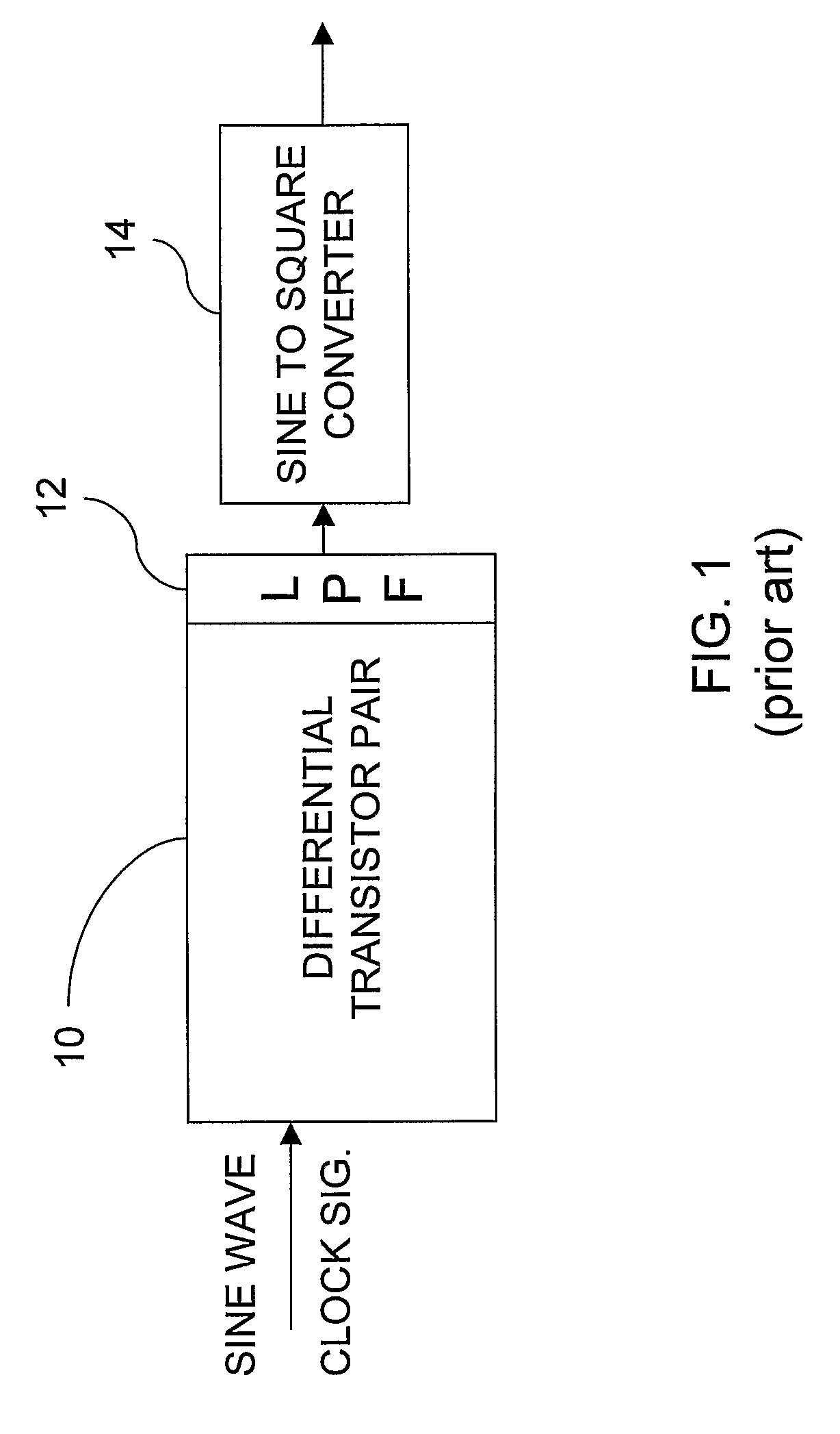
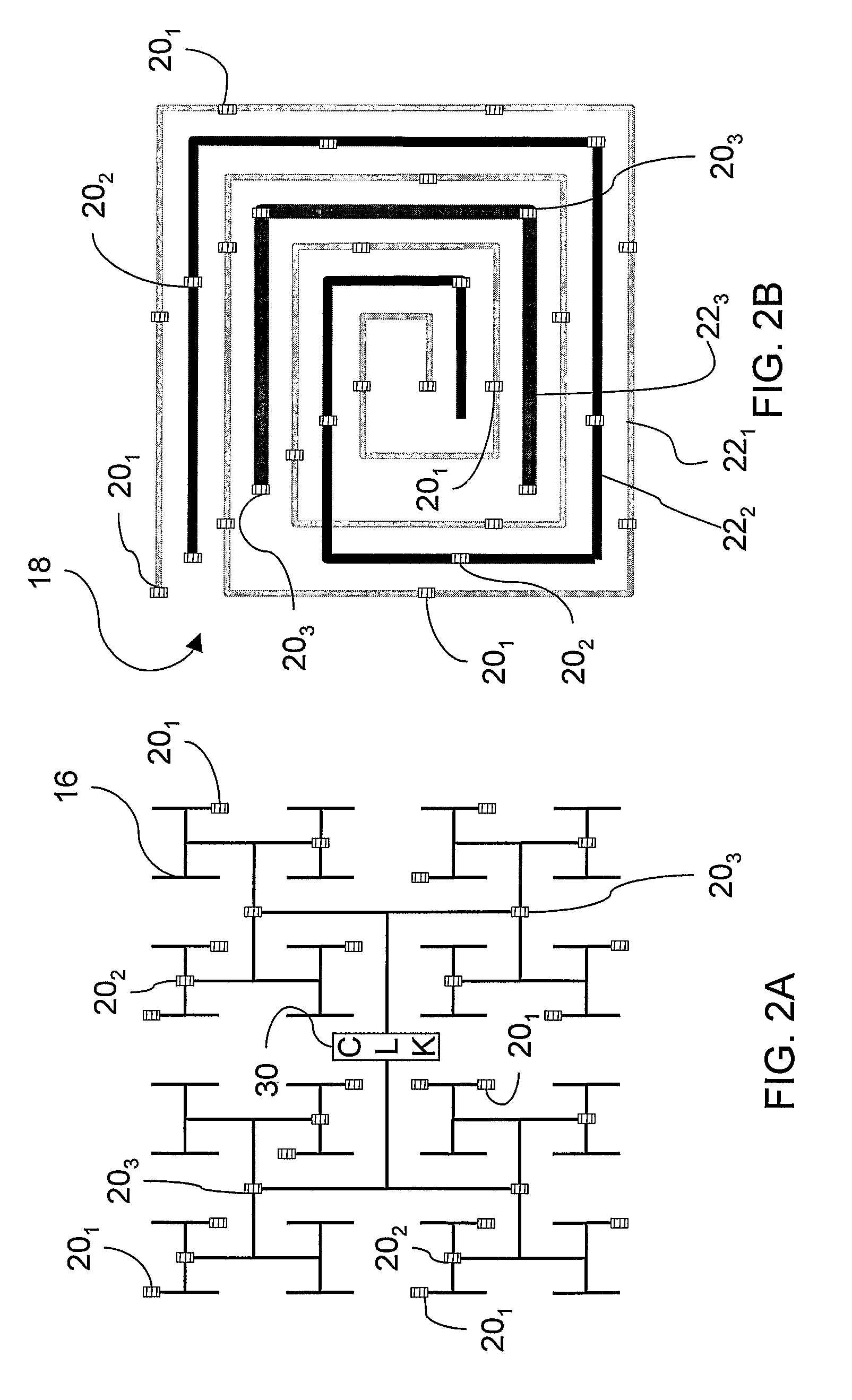
[0017]The invention provides clock distribution methods and circuits a hybrid structure of a clock distribution tree, e.g., an H-tree, and a differential transmission line shunt to shunt a level of the clock distribution tree, or more preferably, multiple differential transmission line shunts to shunt multiple levels of the clock distribution tree. The clock is distributed as differential signals of periodic waves, e.g., sinusoidal waves. Even at high frequencies, e.g., 10 GHz and higher, the clock distribution method of the invention provides an output to levels of the clock distribution tree that exhibits very small skew. In a VLSI circuit of the invention, a square-wave clock signal is recovered locally and provided to registers all over the circuit.

[0018]In a preferred embodiment, an H-tree clock distribution circuit is shunted by transmission lines. The transmission lines are driven at discrete points and bent into spiral pattern in order to link the clock drivers of the H-tree...


PUM


Abstract

The invention is directed to a method for clock distribution and VLSI circuits include a clock distribution network. In a method of the invention, a transmission lines are patterned as to connect a clock tree and a periodic waveform clock, preferably a sine waveform, is used to control clock skew, even at frequencies extending into the gigahertz range. In an exemplary embodiment of the invention, an overlay includes differential pairs of transmission lines that connect the drivers of a clock distribution tree. In preferred embodiments of the invention, an H-tree clock distribution scheme is overlayed with a spiral of transmission lines, each realized by a differential conductors and driven using a sinusoidal standing wave to distribute global clock signals into local regions of the chip. Each transmission line connects drivers in the H-tree that are at the same level of the H-tree. In a VLSI chip according to an embodiment of the invention, the transmission line overlay delivers sinusoidal clock signals to local areas that are locally converted into digital clock signals. The invention thus presents a passive technique for clock distribution.

Description

PRIORITY CLAIM[0001]Applicants claim priority benefits under 35 U.S.C. §119 on the basis of Patent Application No. 60 / 573,922, filed May 24, 2004.STATEMENT OF GOVERNMENT INTEREST[0002]This invention was made with Government assistance under NSF Grant No. CCR9987678. The Government has certain rights in this invention.FIELD OF THE INVENTION[0003]The field of the invention is VLSI (very large scale integrated) devices, e.g. microprocessors.BACKGROUND ART[0004]Commercial microprocessors currently operate on clock signals in the gigahertz range. The scale of today's VLSI designs requires the designs to account for clock skew. Clock skew is the relative difference in time that the clock signal reaches different parts of the integrated circuit. In a microprocessor, for example, a global clock signal must be distributed to different parts of the chip. This internal clock signal must be distributed to a large number of clock pins. As clock frequencies increase, the skew can be a limiting fa...

Claims


Application Information

Patent Timeline
Patent Type & Authority Patents(United States)
IPC IPC(8): H03K19/003G06F1/10H03K5/15H03K19/20
CPCG06F1/10H03K5/15013G06F1/04G06F1/06H03K19/096
Inventor CHENG, CHUNG-KUANCHEN, HONGYU
Owner RGT UNIV OF CALIFORNIA
Learn More