
Spectrometer with collimated input light

a spectrometer and input light technology, applied in the field of optical spectroscopy, can solve the problems of low vuv efficiency profile, loss of intensity and spatial resolution in the direction, and inability to design high-efficiency spectroscopic instruments for operation in the vuv, so as to facilitate the alignment of array detectors, improve alignment tolerance, and improve the effect of alignment toleran

Active Publication Date: 2010-03-23
BRUKER TECH LTD
View PDF34 Cites 26 Cited by
  • Summary
  • Abstract
  • Description
  • Claims
  • Application Information

AI Technical Summary

Benefits of technology

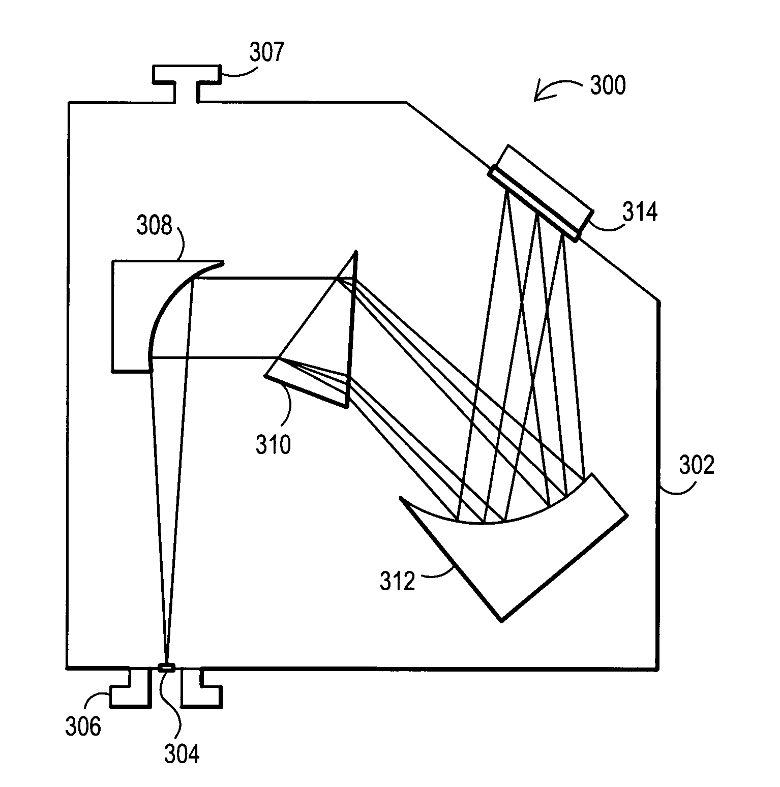
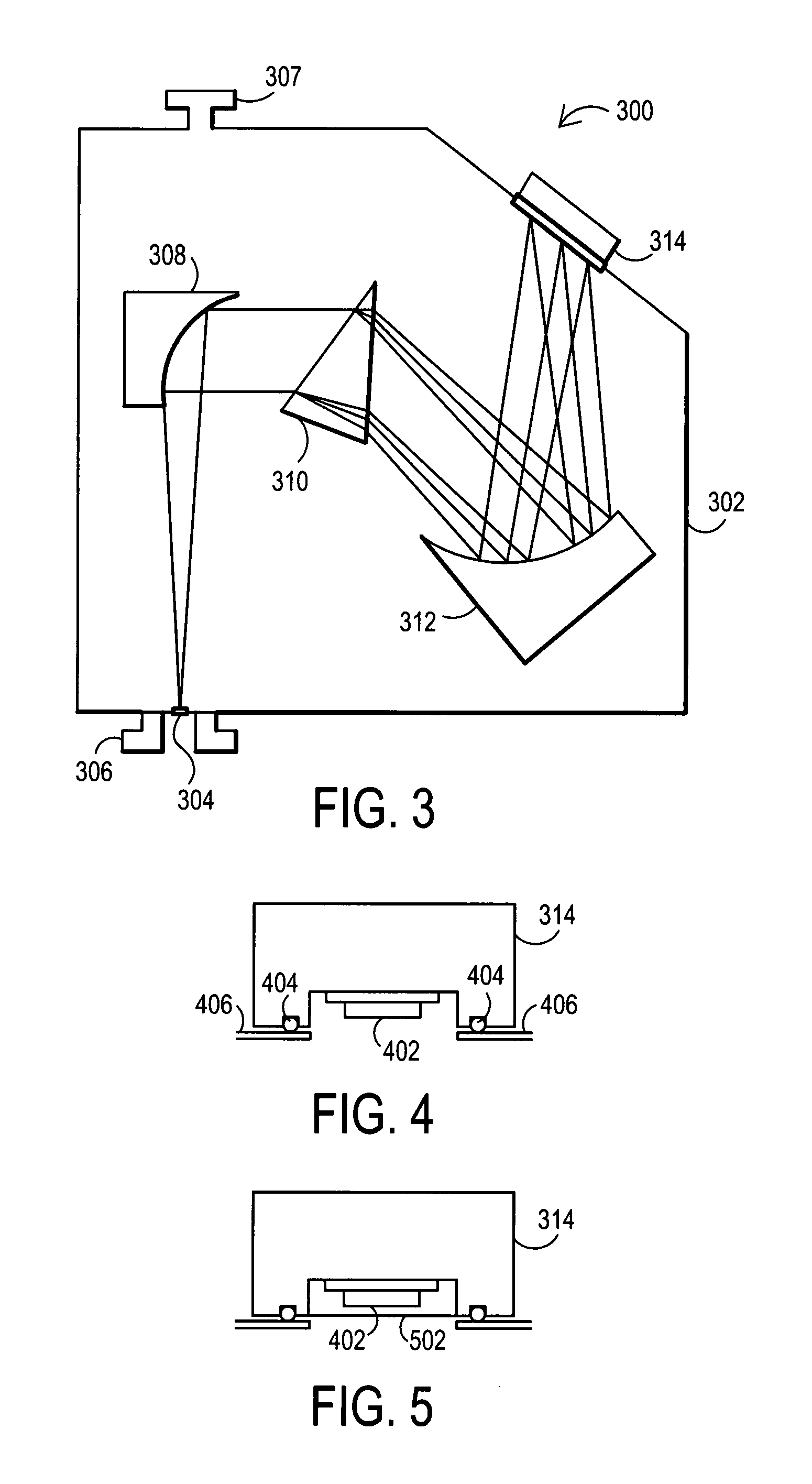
[0016]Another method is provided for improving the alignment tolerance between a spectrometer and an optical system providing input light to the spectrometer. This method may comprise coupling the spectrometer to the optical system and providing collimated light from the optical system to the spectrometer as spectrometer input light so as to provide greater alignment tolerance between the light path of the collimated light and the spectrometer.

Problems solved by technology

As compact high brightness sources are not generally available in this energy space, many of these systems are used in conjunction with massive synchrotron radiation sources at national laboratories.
Designing high efficiency spectroscopic instruments for operation in the VUV has proven to be a formidable challenge.
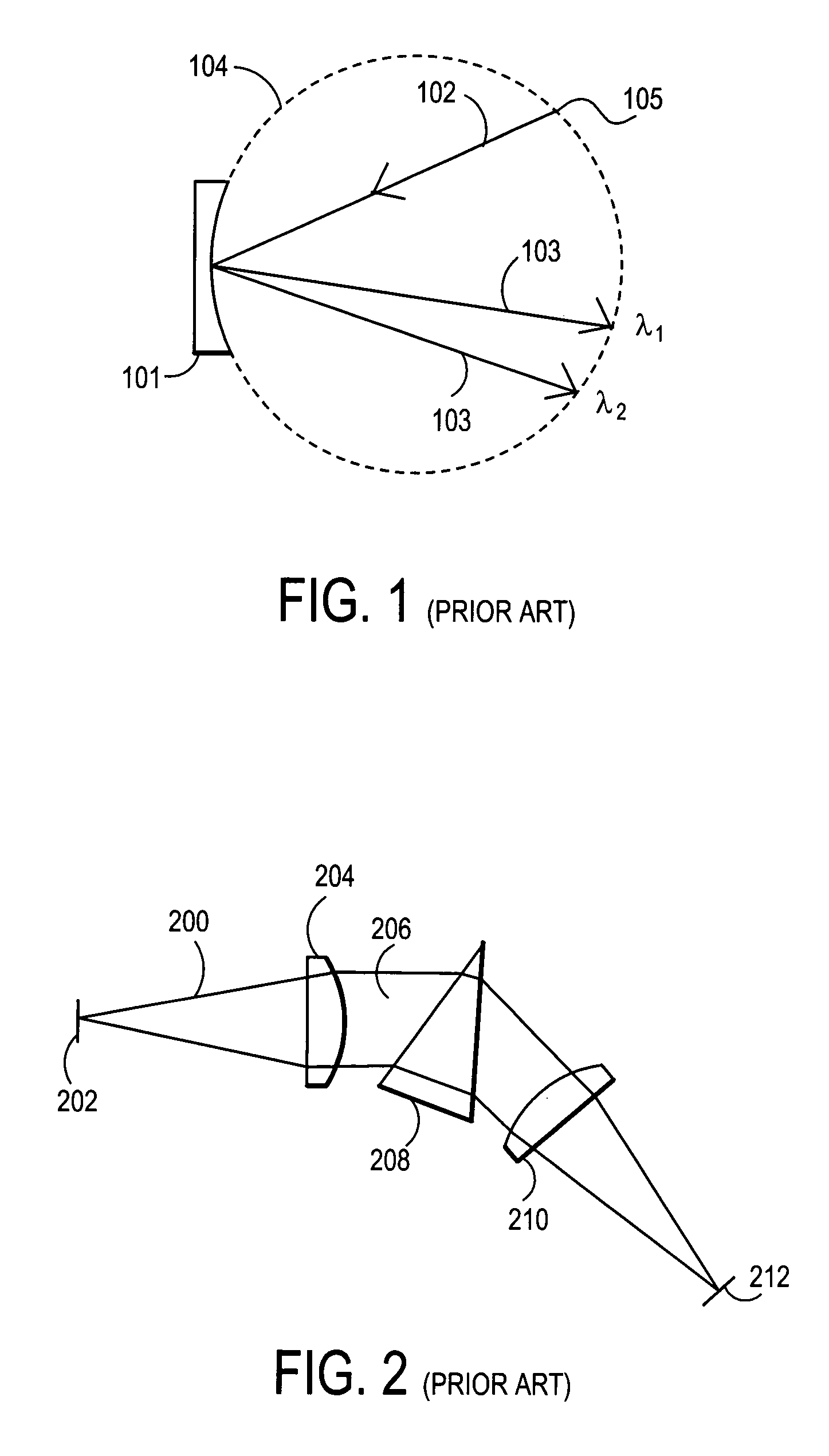
A common drawback of these simple designs is the presence of astigmatism which results in a loss of intensity and spatial resolution in the direction parallel to the entrance slit.
More importantly, while finely ruled gratings can achieve high spectral resolution their VUV efficiency profiles are generally quite low and routinely exhibit complicated wavelength dependencies.
Unfortunately, such systems typically are designed for use in large scale, high-resolution, beam-line experiments and as such, incorporate optical elements (gratings and mirrors) ill-suited for incorporation into small footprint commercial instruments.
For example, such systems may have a very large angle of incidence relative to the grating normal.

Method used


Image

  • Spectrometer with collimated input light
  • Spectrometer with collimated input light
  • Spectrometer with collimated input light

Examples


Embodiment Construction

[0038]To enhance the sensitivity of optical metrology equipment for challenging applications it is desirable to extend the range of wavelengths over which such measurements are performed. Specifically, it is advantageous to utilize shorter wavelength (higher energy) photons extending into, and beyond, the region of the electromagnetic spectrum referred to as the vacuum ultra-violet (VUV). Vacuum ultra-violet (VUV) wavelengths are generally considered to be wavelengths less than deep ultra-violet (DUV) wavelengths, i.e. less than about 190 nm. While there is no universal cutoff for the bottom end of the VUV range, some in the field may consider VUV to terminate and an extreme ultra-violet (EUV) range to begin (for example some may define wavelengths less than 100 nm as EUV). Though the principles described herein may be applicable to wavelengths above 100 nm, such principles are generally also applicable to wavelengths below 100 nm. Thus, as used herein it will be recognized that the...


PUM


Abstract

An optical spectroscopy tool is provided. In one embodiment a highly efficient means by which moderate resolution spectroscopy may be performed in the vacuum ultraviolet (VUV) is described. In one embodiment the techniques can be used as a high throughput spectrometer to spatially disperse wavelengths in and around the VUV in such a manner as to generate a substantially flat field focal plane, suitable for use in combination with an array detector. Some embodiments utilize prism based spectrometers. Some embodiments utilize detector elements that may be movable and / or located within the spectrometer. In some embodiments, collimated light may be provided as an input to the spectrometer.

Description

BACKGROUND[0001]The techniques and systems disclosed herein relate to the field of optical spectroscopy. More specifically, highly efficient means by which moderate resolution spectroscopy may be performed in or below the region of the electromagnetic spectrum referred to as the vacuum ultra-violet (VUV).[0002]Optical spectroscopy techniques have been employed in the characterization of matter for well over a century. While some of the earliest spectroscopic tools employed dispersive prisms to spatially separate wavelengths of light, the vast majority of modern instruments utilize diffraction elements for this purpose. Grating-based systems are generally capable of much higher resolving power and their utilization has become wide spread as a result of significant developments in the production and subsequent replication processes used to manufacture high quality grating elements.[0003]The majority of commonly utilized optical spectroscopic techniques are performed using wavelengths ...

Claims


Application Information

Patent Timeline
Patent Type & Authority Patents(United States)
IPC IPC(8): G01J3/28
CPCG01J3/02G01J3/0208G01J3/021G01J3/0294G01J3/14G01J3/2803
Inventor HARRISON, DALE A.HAYES, ANTHONY T.
Owner BRUKER TECH LTD
Learn More