HV battery cooling with exhaust flow of fuel cell systems

a fuel cell and battery technology, applied in the direction of electric propulsion mounting, electric generators, transportation and packaging, etc., can solve the problems of low fuel cell vehicle driveability, low efficiency of fuel cell vehicles, and relatively high manufacturing costs of meas

Inactive Publication Date: 2010-03-30
GM GLOBAL TECH OPERATIONS LLC
View PDF5 Cites 24 Cited by
  • Summary
  • Abstract
  • Description
  • Claims
  • Application Information

AI Technical Summary

Problems solved by technology

MEAs are relatively expensive to manufacture and require certain conditions for effective operation.
The dynamic power of a fuel cell system is limited.
Further, the time delay from system start-up to driveability and low acceleration of a fuel cell vehicle may not be acceptable.
The voltage cycles can decrease the stack durability.
However, vehicle acceleration may require 100 kW or more of power.
In this particular design, it is typically necessary to cool the battery modules because they generate a significant amount waste heat that could reduce the performance and life of the battery system.
However, this type of liquid cooling system for the battery system has a number of drawbacks in that it is fairly complex to provide the necessary pipes and such to direct the cooling fluid to the battery compartment.
Further, during high load conditions, the ability of the radiator and cooling fan to cool the cooling fluid is reduced, which may not be adequate to cool the battery system to the desired temperature, thus requiring a larger radiator and fan to cool both the fuel cell stack and the battery system under these conditions.
Also, the normal operating temperature of the fuel cell stack, typically between 60° C. and 80° C., is generally too high for proper battery system cooling.

Method used


Image

  • HV battery cooling with exhaust flow of fuel cell systems
  • HV battery cooling with exhaust flow of fuel cell systems

Examples


Embodiment Construction

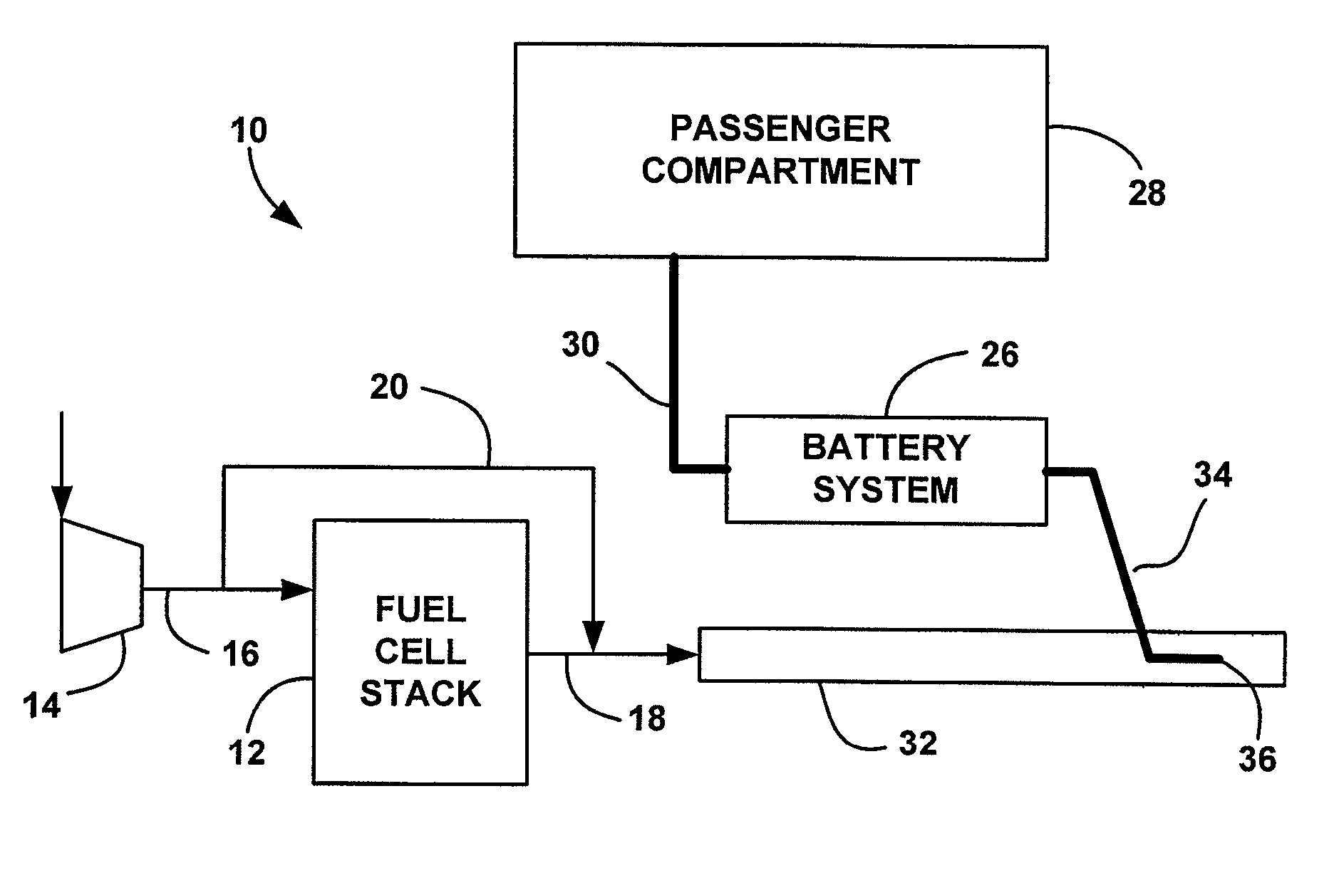
[0016]The following discussion of the embodiments of the invention directed to a fuel cell system for a hybrid vehicle that employs a technique for drawing cooling air from a passenger compartment of the vehicle through a battery sub-system using a cathode exhaust gas flow is merely exemplary in nature, and is no way intended to limit the invention or its applications or uses. For example, the present invention has particular application for a fuel cell hybrid vehicle. However, as will be appreciated by those skilled in the art, the cooling system of the invention may have other applications.

[0017]FIG. 1 is a schematic block diagram of a vehicle system 10 for a fuel cell hybrid vehicle. The system 10 includes a fuel cell stack 12 that receives a cathode input airflow from a compressor 14 on a cathode input line 16. The compressor 14 drives the cathode air through the fuel cell stack 12, and a cathode exhaust gas is output from the cathode side of the fuel cell stack 12 on output lin...


PUM


Abstract

A fuel cell system for a hybrid vehicle that includes a high voltage battery, where the system uses a cathode exhaust gas airflow from a fuel cell stack to draw air through a battery compartment in which the battery is mounted to provide battery cooling. An air intake line is in fluid communication with the passenger compartment of the vehicle and the battery compartment. An ejector line is in fluid communication with the battery compartment and the cathode exhaust gas pipe. The flow of the cathode exhaust gas around the injector pipe creates a low pressure area, which draws air through the battery compartment from the passenger compartment. In one embodiment, a compressor that provides the cathode inlet air to the fuel cell stack is used at low stack output loads, such as during vehicle idle, to direct air through the cathode exhaust gas pipe, and cool the battery system under low load conditions.

Description

BACKGROUND OF THE INVENTION[0001]1. Field of the Invention[0002]This invention relates generally to a battery cooling system for a vehicle and, more particularly, to a battery cooling system for a fuel cell hybrid vehicle, where the battery cooling system uses the exhaust gas flow from a fuel cell stack to create a partial vacuum that draws air through the battery system from the passenger compartment of the vehicle.[0003]2. Discussion of the Related Art[0004]Hydrogen is a very attractive fuel because it is clean and can be used to efficiently produce electricity in a fuel cell. A hydrogen fuel cell is an electro-chemical device that includes an anode and a cathode with an electrolyte therebetween. The anode receives hydrogen gas and the cathode receives oxygen or air. The hydrogen gas is dissociated in the anode to generate free hydrogen protons and electrons. The hydrogen protons pass through the electrolyte to the cathode. The hydrogen protons react with the oxygen and the electr...

Claims


Application Information

Patent Timeline
Patent Type & Authority Patents(United States)
IPC IPC(8): B60K1/00
CPCB60K1/04H01M10/5004H01M10/5016H01M10/5095H01M10/5097H01M16/003H01M10/5067B60K11/06B60K2001/005Y02T90/32H01M2250/20H01M10/625H01M10/663H01M10/6563H01M10/667H01M10/613Y02T90/40Y02E60/50Y02E60/10
Inventor KOENEKAMP, ANDREASWILPSBAEUMER, REINER
Owner GM GLOBAL TECH OPERATIONS LLC
Why Eureka
Try Eureka