Current insulation system for fluid systems

a fluid system and current insulation technology, applied in the direction of sleeve/socket joints, mechanical equipment, static dischargers of aircraft, etc., can solve the problems of equipment malfunction, equipment malfunction, and internal electrical currents that may give way to catastrophic failures or phenomena of the overall structural integrity, so as to reduce maintenance costs, reduce manufacturing and assembly costs, and reduce weight

Inactive Publication Date: 2010-03-30
AIRBUS OPERATIONS SL
View PDF10 Cites 14 Cited by
  • Summary
  • Abstract
  • Description
  • Claims
  • Application Information

AI Technical Summary

Benefits of technology

[0014]An advantage of the system object of the present invention is that the insulating insert is joined to the two parts of the linear element without needing mechanical jointing elements such as bolts, rivets, washers or nuts.
[0015]Another advantage of the system object of the present invention is the leak-tight nature of the joint between the insulating insert and the two parts of the linear element, without needing specific means for it such as gaskets or rubber seals with the subsequent reduction in maintenance costs.
[0016]Another advantage of the system object of this invention is the reduction in manufacturing and assembly costs as the machined pieces made of difficult to elaborate insulating material are eliminated.
[0017]Another advantage of the object of this invention is the reduction in weight resulting from not using specific jointing and leak-tight elements.

Problems solved by technology

Said effect induces internal electrical currents that may give way to catastrophic failures or phenomena for the overall structural integrity.
Electrical equipment malfunction: the electrical discharges caused by lightening striking give way to high levels of current circulating through the outer structure and may therefore introduce electric current through the internal systems either by shunting or induction.
These effects are capable of causing critical equipment malfunction, generating a catastrophic failure.

Method used


Image

  • Current insulation system for fluid systems
  • Current insulation system for fluid systems

Examples


Embodiment Construction

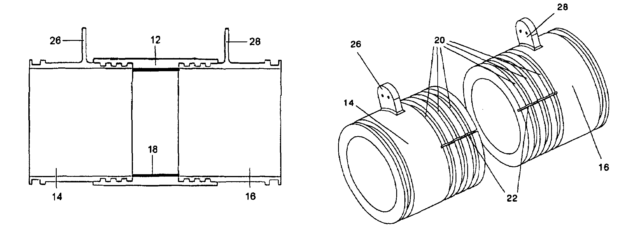
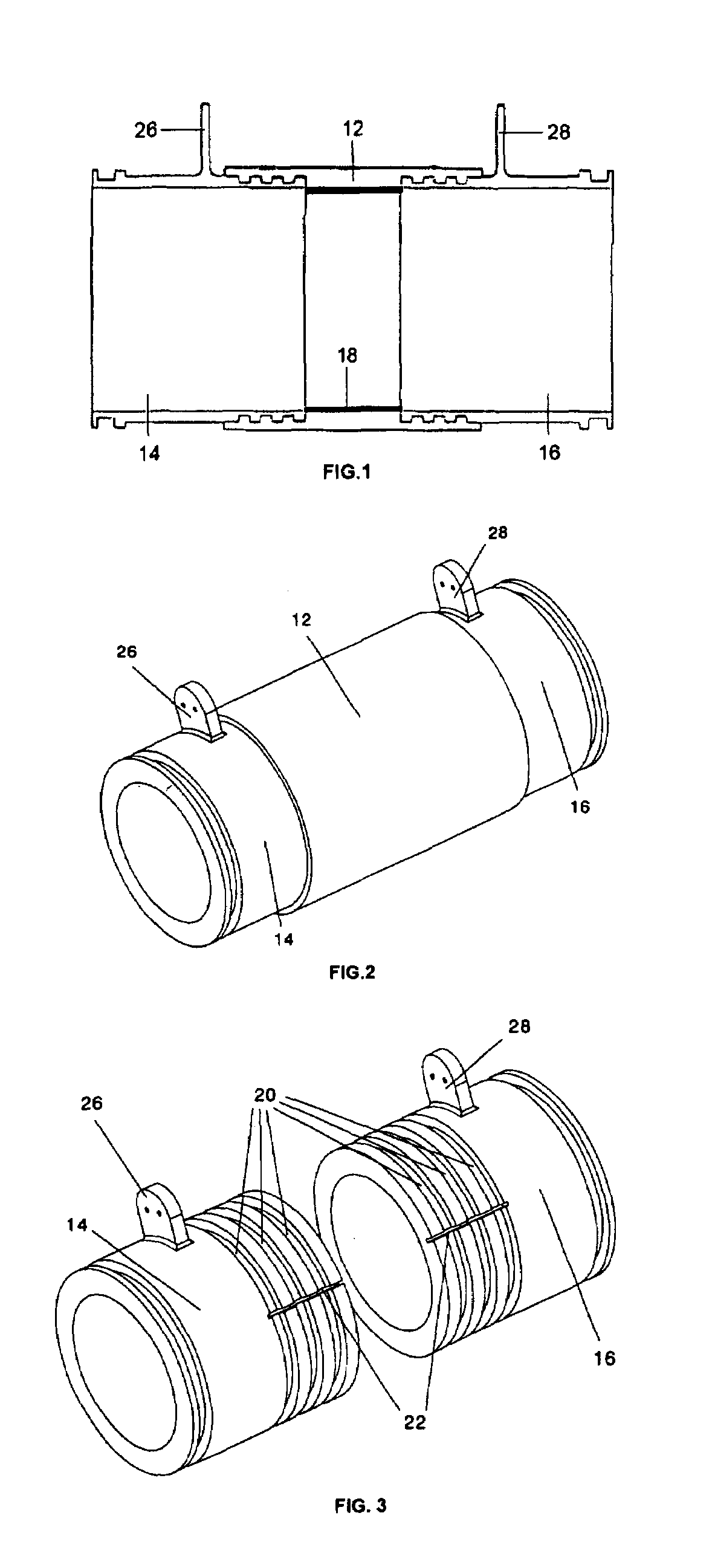
[0022]In FIGS. 1, 2 and 3, which show a preferred embodiment of the invention, it can be seen that the insulating insert 12 is a piece joined in a leak-tight manner to parts 14, 16 of a metal pipe. Such joint occurs when the insulating insert 12 is formed between said parts 14, 16 by means of any suitable technique. Therefore specific jointing and / or leak-tight elements are not used.

[0023]A suitable technique is injection using a suitable mold (not shown) resulting in a cylindrical-shaped insulating insert 12. The injection can be carried out either externally or internally, preventing internal stepping according to needs. Nylon, polyamide and PEEK are some of the preferred insulating materials that can be used.

[0024]The edges of parts 14, 16 of the metal pipe are grooved so as to facilitate the leak-tight joint of the insulating insert 12 formed in situ. For the purpose of this invention, the expression “grooved edges” must be understood in the broadest sense, including any type of...


PUM


Abstract

An electrical insulation system for a linear element forming part of a fluid system subjected to risks of possible external electrical discharges, such as an aircraft fuel system, using an insulating insert (12) between two parts (14, 16) of said linear element, consisting of providing said parts (14, 16) with grooved edges and in forming the insulating insert (12) between them preferably by an injection technique, such that the insulating insert (12) provides an inner duct for the passage of fluid between said parts (14, 16) and covers said grooved edges, assuring the leak-tight joint of the insulating insert (12) with said parts (14, 16).

Description

FIELD OF THE INVENTION[0001]The invention relates to an insulation system for fluid systems subjected to risks of possible electrical discharges using insulating inserts between parts of the linear elements of the fluid system, and more specifically to an insulation system for protecting aircraft fuel systems against electrical discharges caused by lightening striking fuel deposits made of materials with low electrical conductivity.BACKGROUND OF THE INVENTION[0002]Composite materials provide high electrical resistance in comparison with metallic materials. The latter have traditionally been used in the field of aeronautics for the manufacture of structures intended for fuel storage given their mechanical characteristics in relation to the weight of these materials.[0003]The high electrical resistance inherent to composite materials causes a highly relevant induction effect in internal fuel tank systems. Said effect induces internal electrical currents that may give way to catastroph...

Claims


Application Information

Patent Timeline
Patent Type & Authority Patents(United States)
IPC IPC(8): F16L11/12
CPCB64D37/32B64D45/02F16L25/025F16L25/03Y02T50/44Y02T50/40
Inventor FERNANDEZ VIEIRA, JES S
Owner AIRBUS OPERATIONS SL
Why Eureka
Try Eureka