
Flame straightening in a furnace

a furnace and flame straightening technology, which is applied in the direction of lighting and heating apparatus, combustion types, and combustion using lumps and pulverulent fuel, etc., can solve the problems of uneven heating of the reaction chamber i.e. process tubes, affecting the performance of such furnaces, and overheating of some reaction chamber walls

Active Publication Date: 2010-03-30
AIR PROD & CHEM INC
View PDF7 Cites 17 Cited by
  • Summary
  • Abstract
  • Description
  • Claims
  • Application Information

AI Technical Summary

Benefits of technology

[0029]In an embodiment of the invention, the furnace may optionally comprise a means for reducing the combined horizontally projected free jet area at 30% of the average distance from the first interior end to the second interior end.

Problems solved by technology

Undesirable gas flow patterns can deflect flames and cause localized overheating of process tubes thereby affecting the performance of such furnaces.
In the course of implementing new low NOx burner technology in a furnace with an aspect ratio greater than 0.8, the inventors found that substitution of low NOx burners for the conventional burners sometimes produced deflected flames that resulted in the problem of uneven heating of the reaction chambers i.e. process tubes.
This resulted in overheating of some reaction chamber walls, non-uniformity in wall temperatures, large deviations in process gas temperatures from one process header to another, poor radiant efficiency, and may reduce the life of the furnace and its components.
These methods proved unsatisfactory.
Further, some of these methods are not permanent solutions but rather temporary fixes which often reduce the performance of the furnace.
In a furnace where furnace gas patterns are unstable, any flame stabilization or straightening efforts in one region could lead to undesirable effects in another region.
These methods do not eliminate the problem relating to furnace gas interaction with the flames.

Method used


Image

  • Flame straightening in a furnace
  • Flame straightening in a furnace
  • Flame straightening in a furnace

Examples


case 2

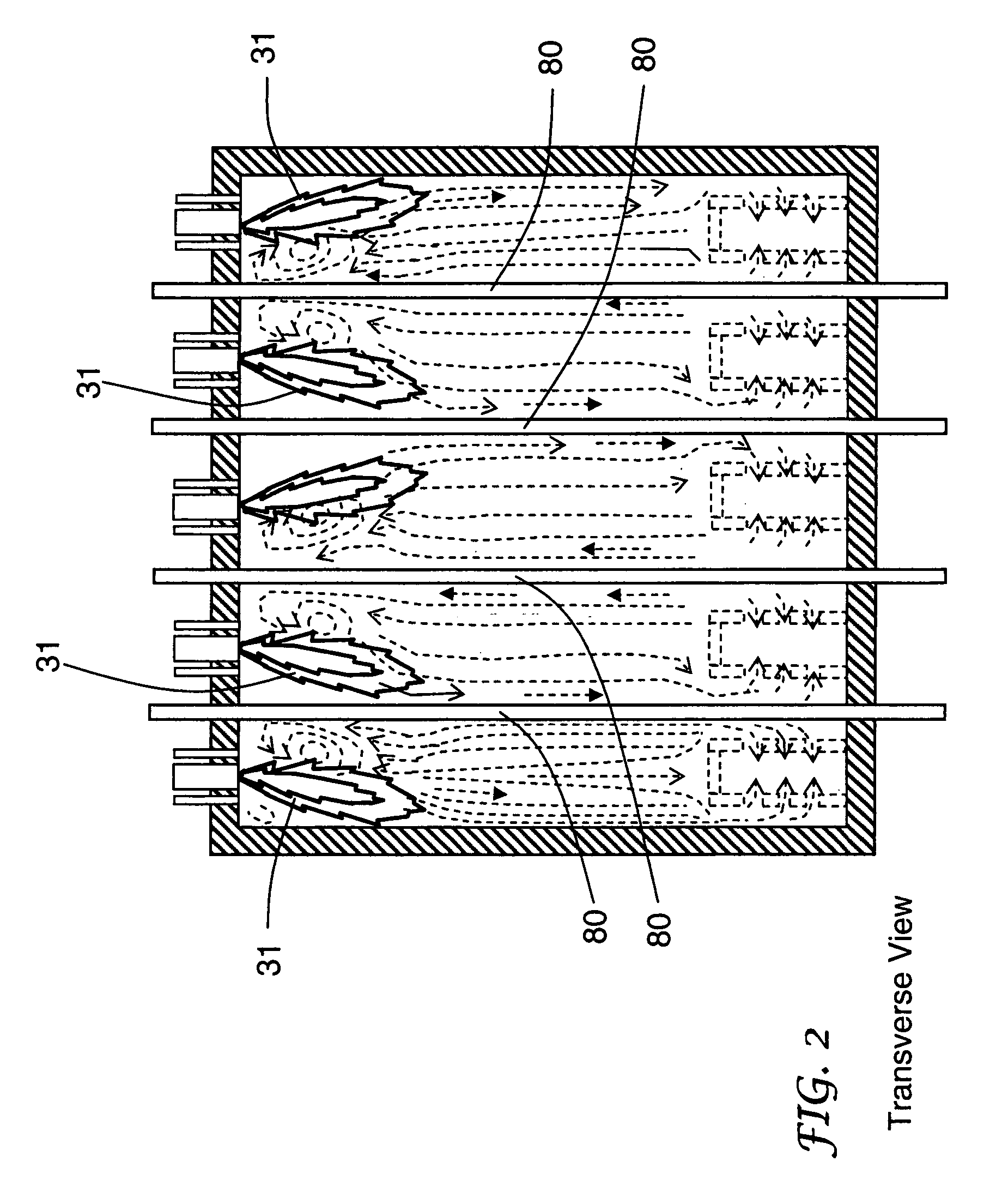
[0059 differs from case 1 because of a reduced area ratio at 30% as a result of five unutilized oxidant conduits (described further below). Fuel conduits associated with the unutilized oxidant conduits were also unutilized.

[0060]These results suggest that for a furnace having an aspect ratio greater than 0.8 and burners with fuel staging, flame impingement on reaction chambers 80 may be avoided if the area ratio at 30% is about 104% or less.

[0061]

TABLE ICase12345Oxidant Outlet Diameter (m)0.3180.3180.3050.3630.426Normalized Reaction Chamber110.790.971.03LengthFurnace Aspect Ratio (Width1.31.30.30.61.3to Row Length)Fuel StagingYesYesYesYesNoArea Ratio at 30%108%104%127%130%128%Flame Impingement on ReactionYesNoNoNoNoChambers

[0062]According to an embodiment of the invention, the combined horizontally projected turbulent free-jet area at 30% of the average distance from the interior end 50 to the interior end 60 is reduced to between 10% and 105% of the horizontally projected area of t...


PUM


Abstract

The present invention relates to a method and furnace for generating straightened flames in a steam methane reformer or ethylene cracking furnace where fuel-staged burners are used. Fuel staging may be used for reducing NOx emissions. Criteria for generating straightened flames are provided. These criteria relate to oxidant conduit geometry and furnace geometry. Techniques for modifying the furnace and / or burners to achieve these criteria are also provided.

Description

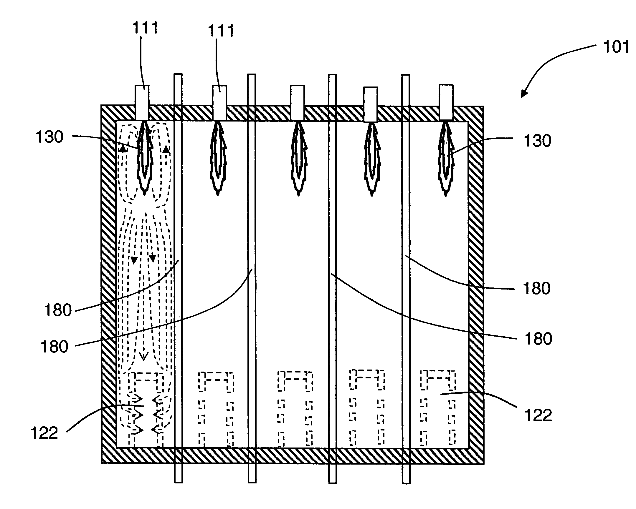
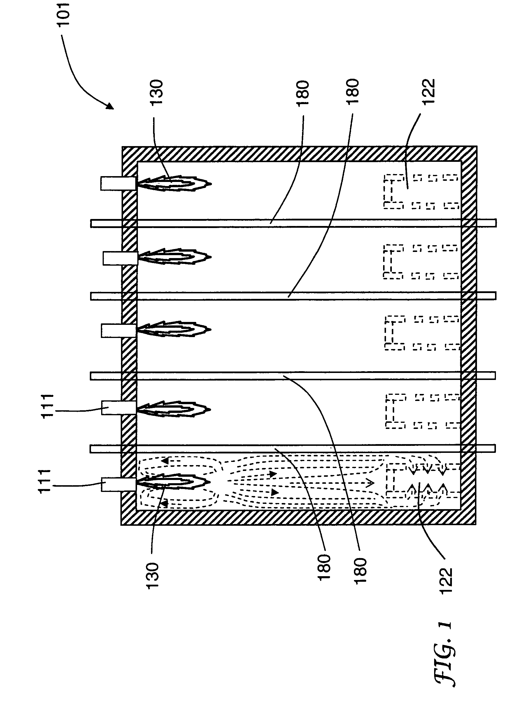
BACKGROUND OF THE INVENTION[0001]The present invention relates to a method and furnace for generating straightened flames in a furnace, and in particular to a method and furnace for generating straightened flames in down-fired and up-fired furnaces having multiple rows of reaction chambers (e.g., process tubes) and multiple rows of low-NOx burners.[0002]Large down-fired and up-fired multi-row furnaces (e.g., reformer furnaces and ethylene cracking furnaces) have complex furnace gas flow patterns. Undesirable gas flow patterns can deflect flames and cause localized overheating of process tubes thereby affecting the performance of such furnaces.[0003]A conventional steam methane reformer furnace 101 with a down-firing configuration is shown in FIG. 1. A feed gas (steam+natural gas) is supplied at the top of process tubes 180, which are filled with reforming catalyst. The feed gas is reformed in the catalyst-filled process tubes 180 to form syngas (primarily H2, CO, CH4, H2O, and CO2),...

Claims


Application Information

Patent Timeline
Patent Type & Authority Patents(United States)
IPC IPC(8): F23C5/00
CPCB01J8/062C01B3/384C10G9/20F23C5/08F23C6/02F23D14/22C01B2203/0233C01B2203/0816F23C2201/102F23C2201/30F23C2900/03002F23C2900/05081F23D14/46F23D14/00
Inventor JOSHI, MAHENDRA LADHARAMLI, XIANMING JIMMYLICHT, WILLIAM ROBERTSLAVEJKOV, ALEKSANDAR GEORGIDIMARTINO, SR., STEPHEN PAUL
Owner AIR PROD & CHEM INC
Learn More