Filtering and route lookup in a switching device

a switching device and filtering technology, applied in data switching networks, instruments, frequency-division multiplexes, etc., can solve the problems of inefficiency of conventional routers in a number of respects, design trade-offs (cost), and inability to connect in the switch, so as to reduce the occurrence of dropping packets, reduce the size of the output buffer, and reduce the effect of packet drop

Inactive Publication Date: 2010-03-30
JUMIPER NETWORKS INC
View PDF38 Cites 76 Cited by
  • Summary
  • Abstract
  • Description
  • Claims
  • Application Information

AI Technical Summary

Benefits of technology

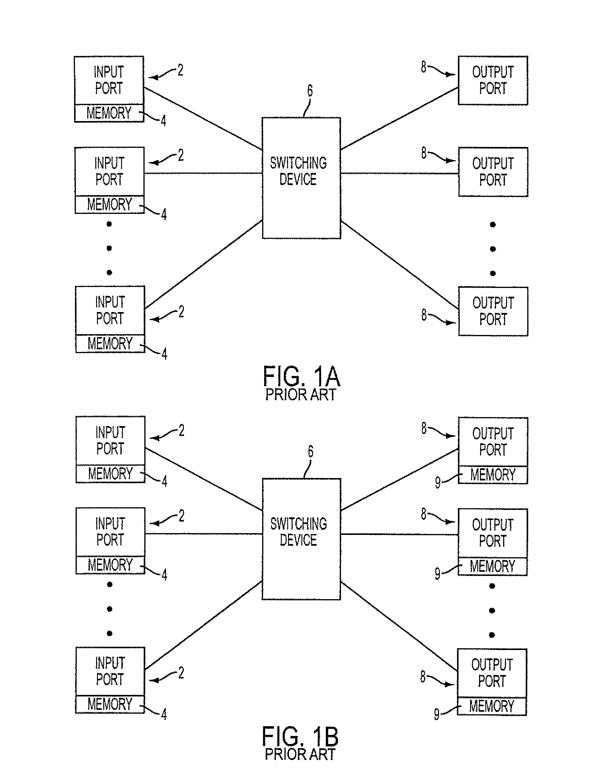
[0009]To minimize the occurrence of dropping packets, designers developed non head-of-line blocking routers. Referring now to FIG. 1B, a conventional non head-of-line blocking router includes a plurality of input ports 2 each including an input buffer (memory) 4, a switching device 6 and a plurality of output ports 8 each having an output buffer (memory) 9. In order to provide non head-of-line blocking, each output port 8 is configured to include an output buffer so that each output port can simultaneously be outputting packets as well as receiving new packets for output at a later time. As the size of the output buffer is increased, fewer packets are dropped due to head-of line blocking at input ports.

Problems solved by technology

Blocking refers to a condition in which a connection cannot be made in the switch due to the unavailability of the desired output port (the port is busy, e.g., routing another packet from a different input port).
Unfortunately, conventional routers are inefficient in a number of respects.
However, design trade-offs (cost) often necessitate smaller buffers for each port.
With the smaller buffers, the possibility arises for packets to be dropped due to blocking conditions.
While excess memory capacity typically exists in the router (due to the varied usage of the input ports), no means for taking advantage of the excess is afforded.
However, these designs are even more inefficient in terms of memory capacity and cost.
Even more excess memory capacity typically exists in the router (due to the varied usage of the input ports and output ports), yet no means for taking advantage of the excess is afforded.

Method used


Image

  • Filtering and route lookup in a switching device
  • Filtering and route lookup in a switching device
  • Filtering and route lookup in a switching device

Examples


counting example

[0472]Filters can be configured to target the exact nature of traffic on a network and, by counting different packets, provide visibility into the packet types that are traversing the system. For example, a filter can be configured that counts all packets sourced from a range of specific / 24 IP address prefixes entering a network by way of a peering connection.

Real-Time Packet Counters

[0473]Packet counting provides a very powerful tool for characterizing traffic on service provider networks. Packet counters can be used to perform capacity planning and identify bottlenecks in the core of a network; determine the types of packets transiting or destined to the core and the relative ratio of one packet type to another (for example, the ratio of mail versus FTP packets); and analyze attacks on service provider or subscriber networks by counting packets for commonly used attacks (e.g., ICMP request response packets used in a smurf attack).

[0474]The ASIC-based packet processor supports real...


PUM


Abstract

Methods and devices for processing packets are provided. The processing device may Include an input interface for receiving data units containing header information of respective packets; a first module configurable to perform packet filtering based on the received data units; a second module configurable to perform traffic analysis based on the received data units; a third module configurable to perform load balancing based on the received data units; and a fourth module configurable to perform route lookups based on the received data units.

Description

RELATED APPLICATIONS[0001]This is a continuation of U.S. patent application Ser. No. 10 / 017,719 entitled “Filtering and Route Lookup in a Switching Device” for Ferguson et al. filed on Dec. 14, 2001 which is a continuation-in-part of co-pending U.S. patent application Ser. No. 09 / 550,413 entitled “Filtering and Route Lookup in a Switching Device” for Ferguson et al. filed on Apr. 17, 2000, the content of which are hereby incorporated by reference.[0002]Moreover, this application claims the benefit of the filing dates of the following provisional patent applications for any inventions disclosed therein in the manner provided by 35 U.S.C. §112, ¶1: U.S. Provisional Application No. 60 / 258,882 entitled “Internet Processor” for Ferguson et al. filed on Jan. 2, 2001; U.S. Provisional Application No. 60 / 258,886 entitled “Internet Processor” for Ferguson et al. filed on Jan. 2, 2001; U.S. Provisional Application No. 60 / 258,887 entitled “Internet Processor” for Ferguson et al. filed on Jan. ...

Claims


Application Information

Patent Timeline
Patent Type & Authority Patents(United States)
IPC IPC(8): H04L12/26
CPCH04L49/3009H04L63/0227H04L12/2697H04L43/028H04L43/50H04L45/00H04L45/60H04L45/745H04L45/7457H04L47/10H04L47/125H04L47/20H04L47/2441H04L47/32H04L67/1002H04L69/22H04L49/25H04L49/205H04L49/3036H04L49/3072H04L43/022H04L45/74591H04L67/1001H04L45/7452
Inventor FERGUSON, DENNIS C.PATEL, RAJIVCHEUNG, GERALDSINDHU, PRADEEP
Owner JUMIPER NETWORKS INC
Why Eureka
Try Eureka