Large effective area fiber with GE-free core

Active Publication Date: 2010-03-30
CORNING INC
View PDF18 Cites 45 Cited by
  • Summary
  • Abstract
  • Description
  • Claims
  • Application Information

AI Technical Summary

Benefits of technology

[0014]provide attenuation less than 0

Problems solved by technology

High power systems often suffer from non-linear optical effects, including self-phase modulation, four-wave-mixing, cross-phase modulation, and non-linear scattering processes, all of which can cause degradation of signals in high powered systems.
In addition, other optical fiber attributes, such as attenuation, are a major contributing factor to the degradation of the signal.
Generally, an optical waveguide fiber having a large effective area (Aeff) reduces non-linear optical effects, including self-phase modulation, four-wave-mixing, cross-phase modulation, and non-linear scatteri

Method used


Image

  • Large effective area fiber with GE-free core
  • Large effective area fiber with GE-free core
  • Large effective area fiber with GE-free core

Examples


embodiment (

Embodiment(s) of the Invention

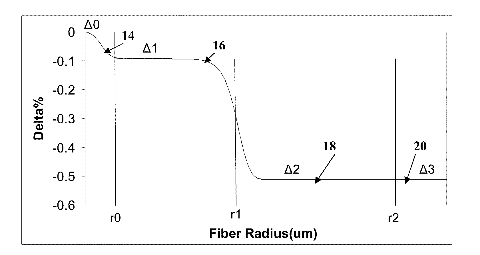
[0037]Reference will now be made in detail to the present embodiment(s) of the invention, examples of which are illustrated in the accompanying drawings. Whenever possible, the same reference numerals will be used throughout the drawings to refer to the same or like parts. One embodiment of the optical fiber of the present invention is shown in FIG. 1A, and is designated generally throughout by the reference numeral 10. The waveguide fiber 10 includes a core 12 having an effective area of at about 90 μm2 or more at a 1550 nm wavelength (for example 90 μm2to 160 μm2, or 100 μm2to 160 μm2 at a 1550 nm wavelength), and α value 12≦α≦25, and a cladding 20 surrounding the core. A typical range of α values is 14 to 20, for example 15≦α≦17. The exemplary refractive index profile (relative refractive index delta, vs. radius) of this fiber shown schematically in FIG. 1B.

[0038]The core 12 is Ge free and comprises a central core region 14, a first annular core regi...

examples

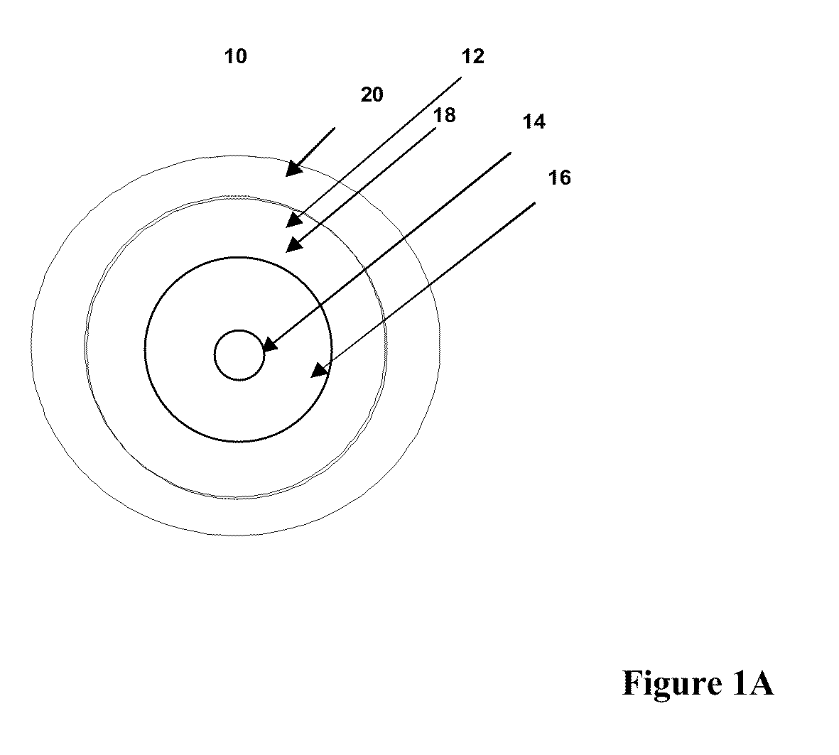
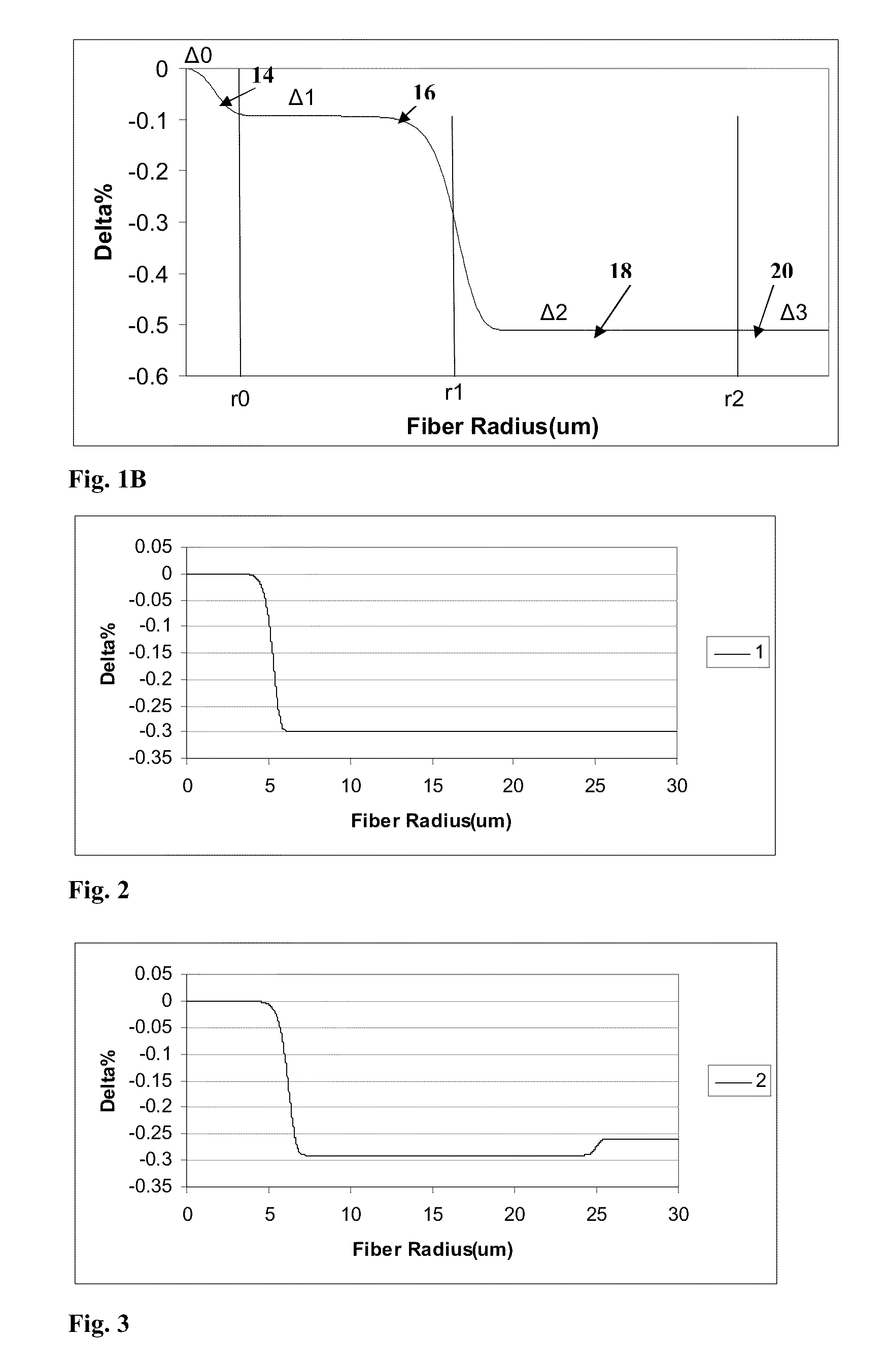
[0046]The invention will be further clarified by the following examples.

[0047]Tables 1-2 list characteristics of Examples 1-15 of an illustrative set of fiber embodiments. FIGS. 2-16 show the refractive index profiles corresponding to Examples 1-15, respectively. In the optical fiber embodiments of Examples 1-15, Δ0=0; −0.065% ≦Δi(r=2.5 μm) ≦0%, −0.065% ≦Δ1MAX≦0. %, −0.5% ≦Δ2MIN≦−0.275%, −0.4% ≦Δ3≦−0.2%, and r2 / r1 is 2.17≦r2 / r1≦5.7 and r20 may be somewhat larger or smaller than 0% (relative to silica), depending on whether updopants or downdopants are present in the center core region 14. Although some embodiments of the optical fibers 10 have alpha values between 12 and 25, optical fiber embodiments of Examples 1-9 have alpha values in the range of 13-15. Optical fiber embodiments of Examples 10-15 have alpha values of about 20.

[0048]The modeled profile parameters of these exemplary fibers are summarized in Table 1A. The values for r3 correspond to the outer diameter of the claddin...


PUM


Abstract

An optical waveguide fiber comprising:
(i) a Ge free core having an effective area of 90 μm2 to 160 μm2, at a 1550 nm wavelength, and α value 12≦α≦25, said core comprising:
(a) a central core region extending radially outwardly from a centerline to a radius r0≦2 μm, and having a relative refractive index percent profile Δ0(r) wherein −0.1% ≦Δ0(r) ≦0.1%, and wherein the central core region has a maximum relative refractive index, Δ0MAX,
(b) a first annular core region surrounding and directly adjacent to the central core region and extending to an outer radius r1, wherein 4.8 μm ≦r1≦10 μm, and having a relative refractive index percent profile, Δ1(r), and a minimum relative refractive index, Δ2MIN, and the relative refractive index measured at a radius r=2.5 μm being −0.15≦Δ1(r=2.5 μm) ≦0, and Δ0MAX ≧Δ1(r=2.5 μm);
(c) a fluorine doped second annular region surrounding and directly adjacent to the first annular core region and extending to a radius 13 μm ≦r2≦30 μm and having a negative relative refractive index percent profile, Δ2(r), with a minimum relative refractive index Δ2MIN being:
Δ2MIN1(r=2.5 μm), and −0.7% ≦Δ2MIN≦−0.28%; and
(ii) a cladding surrounding the core and having a relative refractive index percent Δc (r) in % measured relative to pure silica, and Δc (r)=Δ2MIN±0.3%;
wherein the relative refractive index profile of the optical fiber is selected to provide attenuation of no more than 0.175 dB/km at the wavelength of 1550 nm.

Description

BACKGROUND[0001]1. Field of the Invention[0002]The present invention relates generally to optical fibers, and particularly to large effective area optical fibers with pure silica core and low attenuation.[0003]2 Technical Background[0004]Optical amplifier technology and wavelength division multiplexing techniques are typically required in telecommunication systems that provide high power transmissions for long distances. The definition of high power and long distances is meaningful only in the context of a particular telecommunication system wherein a bit rate, a bit error rate, a multiplexing scheme, and perhaps optical amplifiers are specified. There are additional factors, known to those skilled in the art, which have impacted upon the definition of high power and long distance. However, for most purposes, high power is an optical power greater than about 10 mW. High power systems often suffer from non-linear optical effects, including self-phase modulation, four-wave-mixing, cro...

Claims


Application Information

Patent Timeline
IPC IPC(8): G02B6/02G02B6/36
CPCG02B6/02019G02B6/0281G02B6/0283G02B6/03627G02B6/0365G02B6/028G02B6/036
Inventor MISHRA, SNIGDHARAJ KUMAR
Owner CORNING INC
Why Eureka
Try Eureka