Mixer and mixing method for producing gypsum slurry

a technology of gypsum board and mixing method, which is applied in the direction of ceramicware, manufacturing tools, surface layering apparatus, etc., can solve the problems of insufficient mixing inability to ensure the mixing condition of slurry and foam, and inability to ensure the mixing condition of foam and slurry, etc., to achieve significant and useful effects, the productivity of lightweight gypsum boards is considerably improved

Active Publication Date: 2010-04-06
YOSHINO GYPSUM CO LTD
View PDF22 Cites 29 Cited by
  • Summary
  • Abstract
  • Description
  • Claims
  • Application Information

AI Technical Summary

Benefits of technology

[0034]Besides the factor of the quantity of water, the specific gravity of slurry primarily depends on the quantity of foam mixed in slurry. As a precondition for stabilizing the specific gravity, it is necessary to uniformly mix the foam into the slurry. According to the present invention, the foam feeding port opens on the annular wall on the side of the slurry outlet port upstream in the rotational direction of the rotary disc of the mixer (direction opposite to the rotational direction), or opens on the hollow connector section. The foam feeding port feeds the foam from the wall surface of the annular wall to the slurry immediately before the opening of the slurry outlet port, or feeds the foam to the slurry in the hollow connector portion. Conventionally, the foam has been fed from the upper face (upper plate) of the mixer. In the present invention, however, the foam is fed from the circumferential wall or the hollow connector section of the mixer to be mixed with the slurry, and the foam is further mixed with the slurry in the slurry delivery conduit located downstream, whereby the foam can be uniformly mixed with the slurry in a condition of an increased flow rate of the slurry. In addition, the foam is substantially unaffected by impact of agitation of the mixer, so that a quantity of loss of the foam is decreased, and therefore, the consumption of foaming agent can be considerably reduced. Thus, the mixer can continuously supply the slurry uniformly mixed with the foam to a predetermined area, section, equipment and so forth in the gypsum board producing apparatus, even if the flow rate of slurry is increased owing to speeding up of the gypsum board production rate. Such a mixer can uniformly mix the slurry with the foam even in a condition of an increased flow rate of slurry equal to or higher than 1 m3 / minute.
[0037]More preferably, the hollow connector section has wall surfaces (47a, 47b) on the sides upstream and downstream in the rotational direction, these wall surfaces forming a slurry passage in the section. The wall surface (47a) on the upstream side is oriented at an angle ranging from 90° to 120° with respect to a normal line (G) of the housing. If desired, the wall surfaces (47a, 47b) on the upstream and downstream sides are located in parallel. More preferably, the wall surface (47b) on the downstream side is positioned at a sharp angle relative to a circumferential inside surface of the annular wall so as to prevent the gypsum slurry in the slurry passage from flowing backward or returning to the peripheral zone (slurry drifting zone) of the mixing area.
[0043]The mixing method of the present invention comprises a step for slurry preparation in the mixing area (the first mixing step) and a step for feeding and mixing of the foam to the slurry (the second mixing step). The foam is fed to the slurry in a route of slurry from the peripheral zone via the slurry outlet port to the slurry delivery conduit, and the slurry is subjected to shearing force so that it is to be mixed with the foam, immediately after supply of the foam. The foam is mixed into the slurry without influence of defoaming effect due to agitation impact of the mixer, and mixed with the slurry at the slurry outlet port or downstream thereof. Therefore, the required consumption of foaming agent can be considerably reduced. Further, the foam is uniformly mixed with the slurry in the second mixing step, and therefore, the flow rate of slurry can be increased.
[0049]According to the present method of producing gypsum boards, productivity of lightweight gypsum boards is considerably improved, and therefore, significant and useful effects can be obtained particularly in production of lightweight gypsum boards.

Problems solved by technology

However, it has been found that, as speeding-up of production of gypsum boards is made and the flow rate of slurry is increased, a phenomenon occurs in which the foam and the slurry are not uniformly mixed.
That is, if speeding up of production of gypsum boards is made, a desirable mixing condition of the slurry and the foam can not be ensured by the mixer disclosed in JP 8-25342.
However, the mixer in JP 11-501002 does not have a structure corresponding to the slurry delivery conduit, and the slurry for core is directly discharged to the gypsum board liner paper through the discharge conduit.
For this reason, the foam fed from the foam feeding port on the discharge conduit or its vicinity can not be sufficiently mixed nor dispersed in the slurry when the flow rate of slurry is increased.
Therefore, the mixer of this arrangement can run into difficulties when being applied to the speeding up of production rate of gypsum boards.
② Since such an air space is formed, solidified gypsum (residuum) is produced in the canister, and this results in clogging of the slurry supply passage;
However, the foam tends to stay in a center area of the canister.
Therefore, a portion of slurry having a high density unfavorably separates from the foam with a relatively low density (It follows that the canister takes a disadvantageous action from an aspect of uniform mixing of the slurry and the foam.)
However, an unstable mixing condition of the foam and the slurry may be caused also in this arrangement of the mixer, when a production rate of gypsum boards is raised and the flow rate of slurry in the slurry conduit is increased.
Such a solidified gypsum (residuum) results in a problem of shearing of gypsum board liner paper, which may cause downtime of gypsum board producing process.
Therefore, this is an obstacle to continuous operation of the gypsum board producing apparatus.
However, this arrangement results in destruction of a relatively large quantity of foam subjected to a strong agitating action, and therefore, the quantity of foaming agent has to be increased, in correspondence with the amount of broken foam.
As the production rate of gypsum boards is increased, this tendency becomes remarkable, and therefore, this is disadvantageous in cost saving of production.
Thus, when an attempt is made for speeding up of the gypsum board production line, the conventional mixer encounters at least one of the problems in uniform mixing of foam, stable supply of slurry in a high flow rate, and consumption of foaming agent.

Method used


Image

  • Mixer and mixing method for producing gypsum slurry
  • Mixer and mixing method for producing gypsum slurry
  • Mixer and mixing method for producing gypsum slurry

Examples


example-1

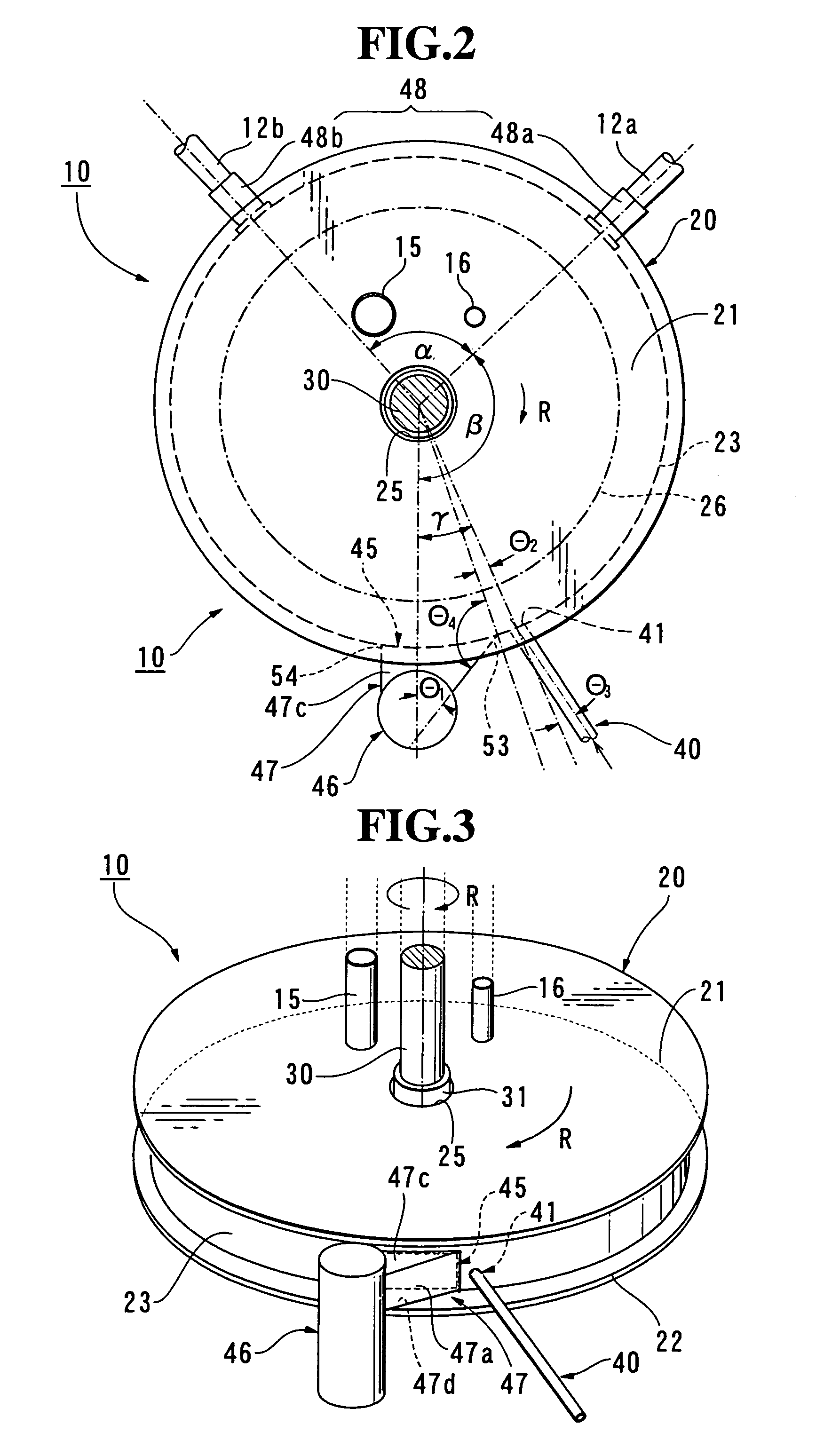
The Mixer of the First Embodiment

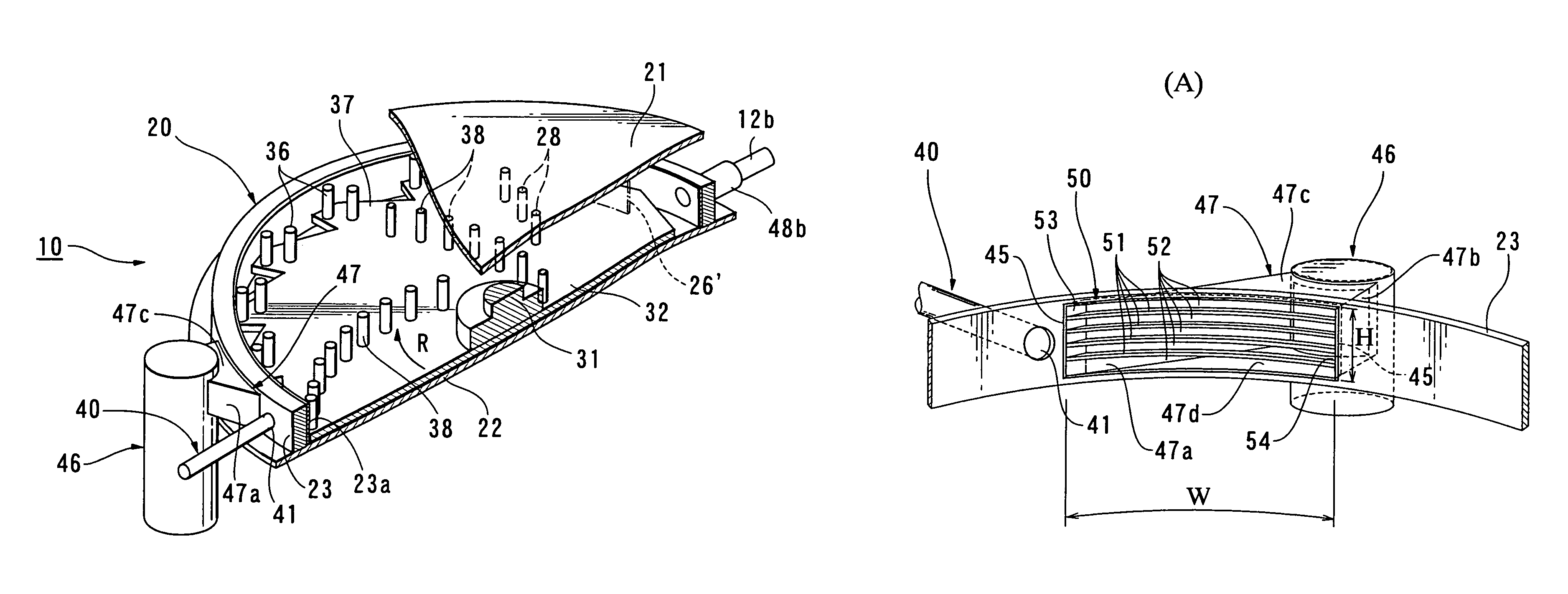
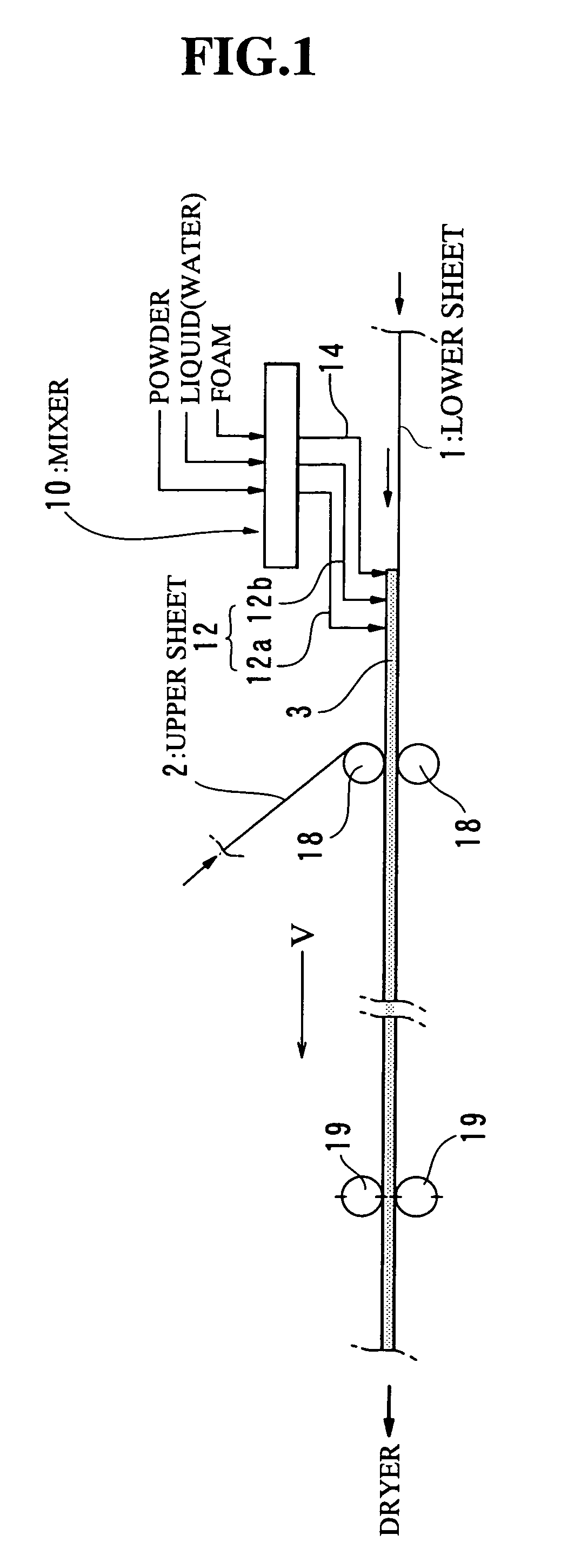
[0144]The mixer 10 as shown in FIGS. 2 to 7 has been used for preparing gypsum slurry, and the foam has been mixed in the slurry by the foam feeding conduit 40 immediately before the slurry enters the slurry outlet port 45. The flow rate of slurry has been set to be 1 m3 / minute, wherein the flow rate of slurry has been defined and measured as the volume of slurry / minute at the time of passing through the section of the forming rollers 18 (FIG. 1). The flow rate of slurry in the Examples and Comparative Examples as set forth below has been based on the same definition. Meanwhile, the slurry is somewhat dried and defoamed while moving from the slurry delivery conduit 46 to the rollers 18 (FIG. 1), and therefore, the volume of slurry / minute at the time of passing through the section of the rollers 18 is reduced by approximately 20%, in comparison with the volume of slurry / minute in the conduit 46. For instance, the volume of slurry / minute=1 m3 / minute at...

example-2

The Mixer of the Second Embodiment

[0145]The attachment 50 (FIGS. 8˜10) has been attached to the slurry outlet port 45 in the mixer 10 of Example-1. The gypsum slurry has been prepared by this mixer 10 and the foam has been mixed into the slurry by the foam feeding conduit 40, immediately before the port 45.

example-3

The Mixer of the Second Embodiment

[0146]The gypsum slurry has been prepared by the same mixer as that of Example-2, and the foam has been mixed into the slurry by the conduit 40, immediately before the port 45. The flow rate of slurry has been set to be 1.5 m3 / minute.


PUM

PropertyMeasurementUnit
thicknessaaaaaaaaaa
thicknessaaaaaaaaaa
angleaaaaaaaaaa

Abstract

The present invention provides a mixer and a mixing method which enable stable supply of slurry at a high flow rate with foam being uniformly mixed therein, and which enable reduction in consumption of foam to be fed to the slurry. The mixer (10) has a housing (20), a rotary disc (32), a slurry outlet port (45), a slurry delivery conduit (46) and a hollow connector section (47). A foam feeding port (41) is disposed in a predetermined position of an annular wall or the hollow connector section. The foam feeding port feeds the foam to the slurry, immediately before the slurry enters the slurry outlet port, or feeds the foam to the slurry in the hollow connector section. The slurry and the foam mix with each other at the slurry outlet port or on its downstream side. The foam is not substantially subjected to agitation impact of the mixer and a quantity of loss of the foam is reduced. The foam is uniformly mixed with the slurry even when the flow rate of slurry is increased, and therefore, the production rate of gypsum boards can be increased.

Description

[0001]This is a nationalization of PCT / JP04 / 007323 filed May 21, 2004 and published in Japanese.TECHNICAL FIELD[0002]The present invention relates to a mixer, a mixing method and a method of producing gypsum boards, which are used in a continuous slurry pouring and casting type of gypsum board production process.TECHNICAL BACKGROUND[0003]Gypsum boards are widely used in various kinds of buildings as architectural interior finish materials, because of their advantageous fire-resisting or fire-protecting ability, sound insulation performance, workability, cost performance and so on. The gypsum boards are known as boards having a gypsum core covered with sheets of paper for gypsum board liner. In general, the gypsum boards are produced by a continuous slurry pouring and casting process. This casting process comprises the following steps:[0004](i) a step of admixing calcined gypsum, adhesive auxiliary agent, set accelerator, foam for reducing a weight, admixtures, additives or the like,...

Claims


Application Information

Patent Timeline
Patent Type & Authority Patents(United States)
IPC IPC(8): B01F3/12B32B38/00B01F7/26B28B19/00B01F27/93B28C5/08B28C5/12B28C5/38
CPCB01F7/00766B28C5/386B28C5/0881B28C5/1269B01F3/04531B28B19/0092B01F23/233B01F27/2711B28C5/06C04B38/106B28C7/16C04B2111/00612C04B28/14B28C5/16B01F23/235
Inventor NAKAMURA, WATARUHIROOKA, YUICHI
Owner YOSHINO GYPSUM CO LTD
Why Eureka
Try Eureka