
Differential two-stage miller compensated amplifier system with capacitive level shifting

a capacitive level shifting and amplifier technology, applied in differential amplifiers, amplifiers with semiconductor devices/discharge tubes, amplifier details, etc., can solve the problems of limited headroom or signal swing of the second stage, limiting the output common mode voltage of the first stage to one vsub>gs /sub>, and severely restricting headroom and input compliance of the first stage. , to achieve the effect of increasing headroom

Active Publication Date: 2010-04-06
ANALOG DEVICES INC
View PDF6 Cites 8 Cited by
  • Summary
  • Abstract
  • Description
  • Claims
  • Application Information

AI Technical Summary

Benefits of technology

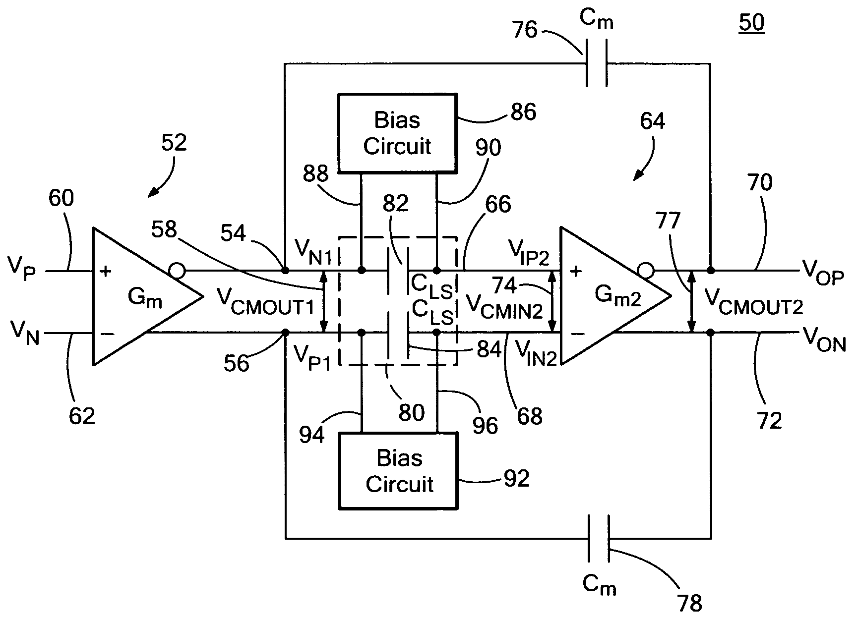
The invention is a differential two-stage Miller compensated amplifier system with capacitive level shifting. It includes a first stage differential transconductance amplifier with an output common mode voltage, a second stage differential transconductance amplifier with non-inverting and inverting inputs and outputs, and a level shifting capacitor circuit that level shifts between the output common mode voltage of the first stage and the input common mode voltage of the second stage. The system also includes first and second Miller compensation capacitors and biasing circuits for charging the capacitors to predetermined voltages. The system provides increased headroom in both stages of the amplifier system and increases the available output common mode voltage swing.

Problems solved by technology

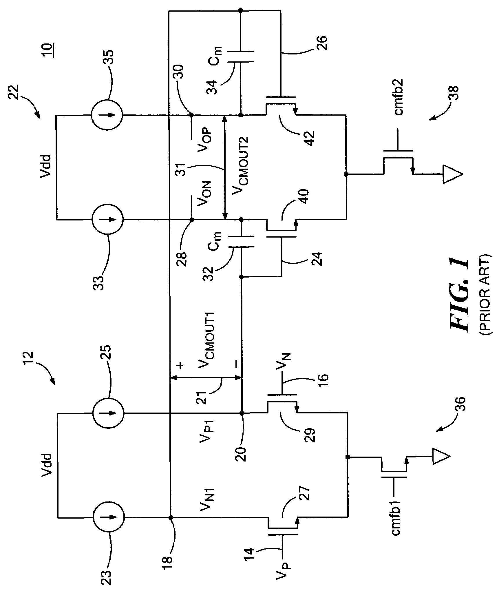
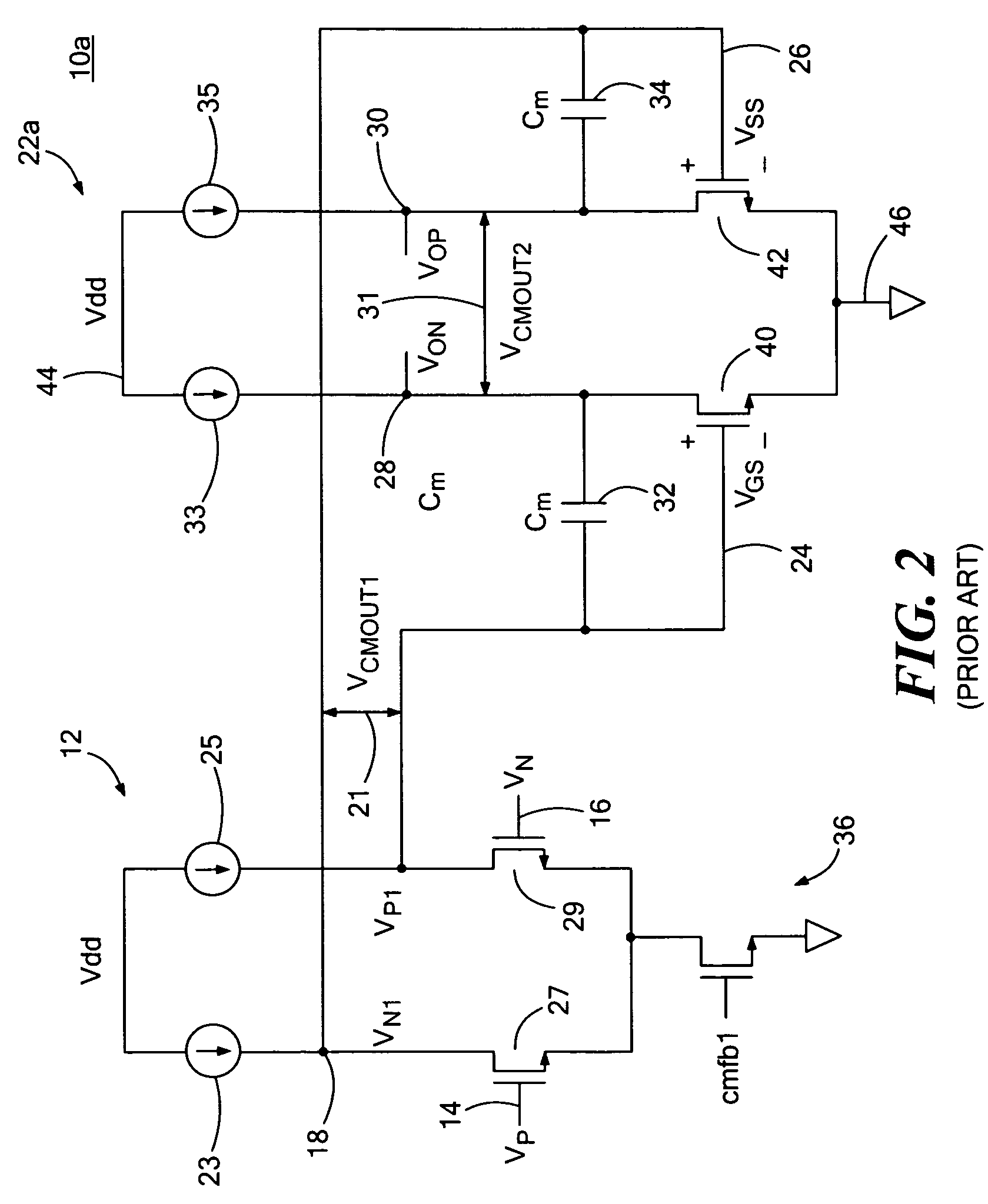
The result is that the headroom or signal swing of the second stage is limited by the output common mode voltage of the first stage.
This is undesirable in many designs where a maximum swing is needed to achieve a high signal-to-noise ratio (SNR).
However, this limits the output common mode voltage of the first stage to one VGS above ground due to the direct connection of the first stage outputs with the inputs of the second stage.
The result is the headroom and input compliance of the first stage is severely restricted, especially if current source devices are used.

Method used


Image

  • Differential two-stage miller compensated amplifier system with capacitive level shifting
  • Differential two-stage miller compensated amplifier system with capacitive level shifting
  • Differential two-stage miller compensated amplifier system with capacitive level shifting

Examples


Embodiment Construction

[0025]Aside from the preferred embodiment or embodiments disclosed below, this invention is capable of other embodiments and of being practiced or being carried out in various ways. Thus, it is to be understood that the invention is not limited in its application to the details of construction and the arrangements of components set forth in the following description or illustrated in the drawings. If only one embodiment is described herein, the claims hereof are not to be limited to that embodiment. Moreover, the claims hereof are not to be read restrictively unless there is clear and convincing evidence manifesting a certain exclusion, restriction, or disclaimer.

[0026]As discussed in the Background section above, conventional two-stage Miller compensated amplifier system 10 includes first differential transconductance amplifier stage 12 with differential inputs VP 14 and VN 16 and differential outputs VN1 18 and VP1 20. Second differential transconductance amplifier stage 22 includ...


PUM


Abstract

A differential two-stage Miller compensated amplifier system with capacitive level shifting includes a first stage differential transconductance amplifier including first and second output nodes and an output common mode voltage, a second stage differential transconductance amplifier including non-inverting and inverting inputs and outputs and an input common mode voltage, and a level shifting capacitor circuit coupled between the first and second output nodes and the non-inverting and inverting inputs for level shifting between the output common mode voltage of the first stage and the input common mode voltage of the second stage.

Description

RELATED APPLICATIONS[0001]This application claims priority to U.S. Provisional Application No. 60 / 636,725 filed Dec. 16, 2004, incorporated by reference herein.FIELD OF THE INVENTION[0002]This invention relates to a two-stage Miller compensated amplifier system with capacitive coupling between the stages that provides for maximum signal swing in low headroom room designs.BACKGROUND OF THE INVENTION[0003]A typical conventional two-stage Miller compensated amplifier system relies on directly coupling the outputs of the first stage with the inputs of the second stage. The result is that the headroom or signal swing of the second stage is limited by the output common mode voltage of the first stage. This is undesirable in many designs where a maximum swing is needed to achieve a high signal-to-noise ratio (SNR).[0004]One conventional two-stage Miller compensated amplifier system attempts to improve this problem by utilizing a wide swing output stage. This results in outputs of the secon...

Claims


Application Information

Patent Timeline
Patent Type & Authority Patents(United States)
IPC IPC(8): H03F3/45
CPCH03F1/086H03F1/14H03F3/45183H03F3/45475H03F3/45654H03F3/45968H03F3/45744H03F2203/45652H03F2200/54H03F2203/45422H03F2203/45424H03F2203/45512
Inventor KELLY, DANIEL F.SINGER, LAWRENCEDECKER, STEVENKOSIC, STEPHEN R.
Owner ANALOG DEVICES INC
Learn More