Method and device for the safe operation of a switching device

a switching device and safe technology, applied in the direction of contact mechanism, circuit-breaking switch, contact welding prevention/breaking, etc., can solve the problem that the operation of this switching device is therefore not safe, and achieve the effect of accelerating the armatur

Active Publication Date: 2010-04-06
SIEMENS AG
View PDF16 Cites 15 Cited by
  • Summary
  • Abstract
  • Description
  • Claims
  • Application Information

AI Technical Summary

Benefits of technology

[0015]At least one embodiment of the present invention identifies potential fault sources and reacts to them appropriately.At least one embodiment of the present invention therefore makes it possible to identify and to react appropriately to contact welding during disconnection and the fact that operation of the switching device is no longer safe, with little complexity.
[0030]Owing to the dominant moving mass of the switching device drive (magnet armature), the closing speed of the moving contact is virtually independent of the wear-dependent mass loss of the moving contact. The closing speed is therefore always the same, when the other conditions are the same. However, the closing speed will increase as the contact pressure decreases, since the magnetic forces with a small armature air gap reach a considerable magnitude and considerably accelerate the armature.

Problems solved by technology

If an opening movement which is shorter than this predetermined opening point is then determined after disconnection, that is to say after deliberate opening of the at least one main contact, then it can be assumed that welding has occurred and that operation of this switching device is therefore not safe.

Method used


Image

  • Method and device for the safe operation of a switching device
  • Method and device for the safe operation of a switching device
  • Method and device for the safe operation of a switching device

Examples


fourth embodiment

[0060]FIG. 6 shows an electrical outline circuit diagram associated with the fourth embodiment, shown in FIG. 5. By way of example, the three main contacts 1 are shown in the central part of FIG. 6 and are operated by way of the contact slide 43, by the control magnet 42 and by the latching mechanism 46. The series circuit including the break contact 41, the switching monitoring device 45 and the actuator 44 for releasing the switching mechanism 46 is illustrated in parallel with two connecting terminals A3 and A4, via which current can be supplied to a field coil for the control magnet 42.

[0061]If a switching voltage for connection of the apparatus is now applied to the terminals A3 and A4, then a current flows through the field coil of the control magnet 42 in order to close the main contact 1. However, in the event of a fault, that is to say if the main contact 1 is welded, the auxiliary contact 44 and / or the switching monitoring device also in fact remain / remains closed, so that...

fifth embodiment

[0064]FIG. 7 shows the apparatus according to an embodiment of the invention, in detail. The upper part of FIG. 7 shows a latching mechanism 46 with an integrated spring energy store as the force element for breaking open a welded main contact 1. The combined latching mechanism 46 acts directly on the moving contact link, when it is initiated, via, for example, two plungers 47, 51 which are mechanically operatively connected to one another. A welded main contact 1 can thus be broken open.

[0065]An actuator 44, as the initiation unit, is connected to the latching mechanism 46 by means of a lever 52 which, for example, is mounted such that it can rotate. The actuator 44 is, for example, a plunger-type armature or a solenoid. The actuator 44 is supplied with current for initiation. This is done in an analogous manner to that for the apparatus shown in FIG. 5 and FIG. 6. That is to say, when the release device 45 and / or the auxiliary contact and the break contact 41 of the control magnet...

sixth embodiment

One particular advantage in this case is that it is possible to detect creeping wear phenomena in the drive mechanism for the electromagnetic drive 60 which then lead to switching operations becoming slower, with a reduced induced voltage ui. FIG. 10 shows the apparatus according to the invention.

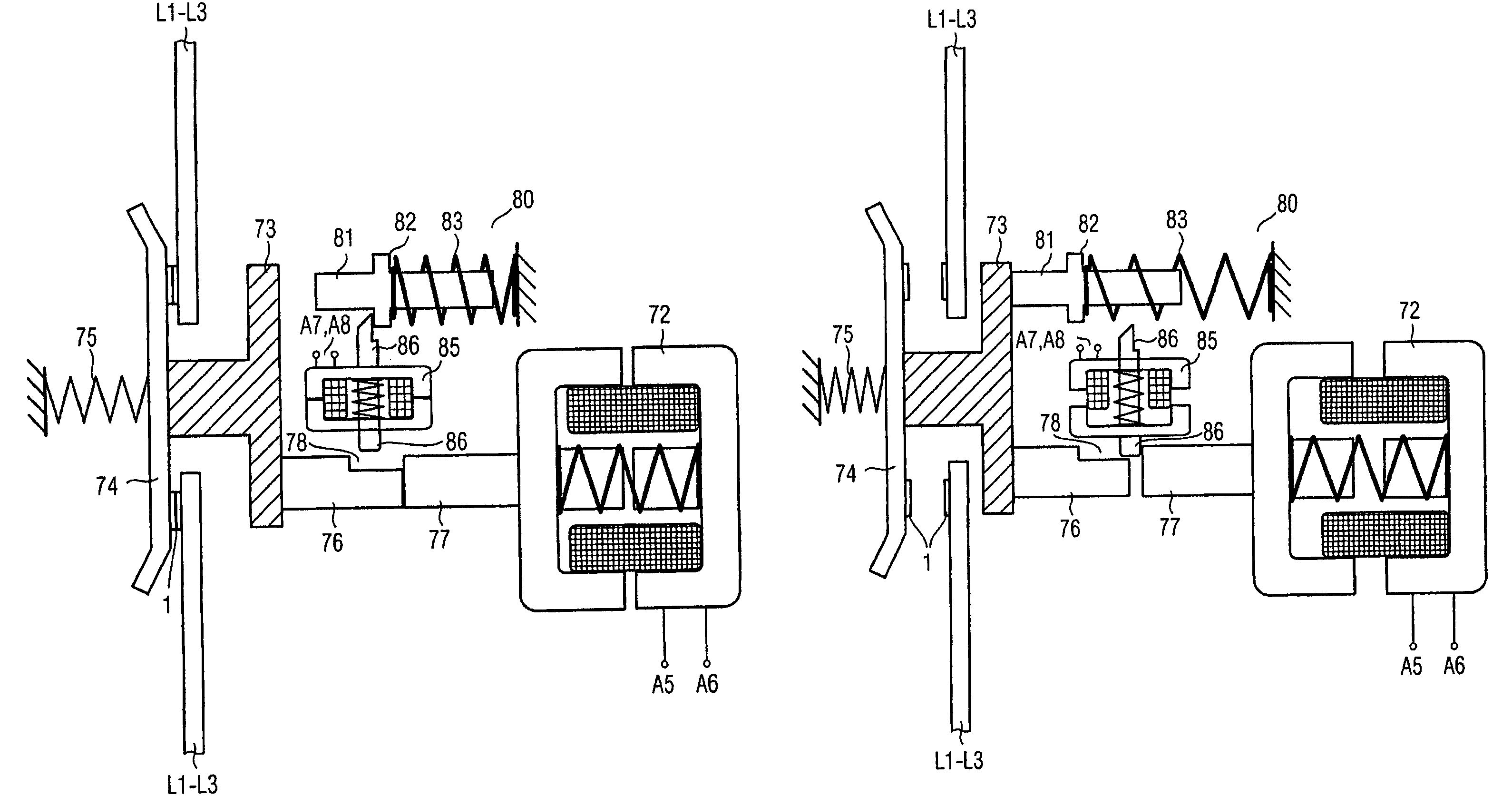
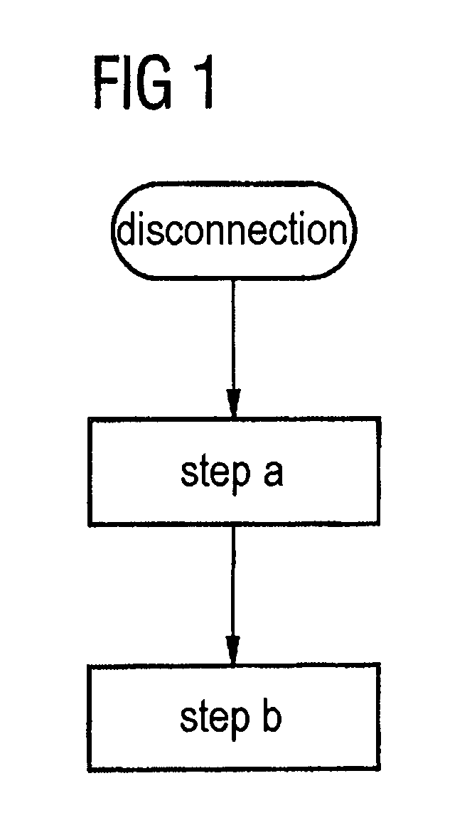
[0080]The major aspect of the apparatus shown in FIG. 10 is that energy is buffered during operation, so that the electrical supply to an evaluation and control unit can still be ensured for a minimum time during disconnection and thus after the removal of the power supply, in order to allow a contact breaking-open device and / or a latching mechanism to be actuated or released, if necessary, if a main contact has become welded.

[0081]By way of example, the embodiment of the present apparatus shown in FIG. 10 relates to an electrical energy store 94 in the form of a capacitor. This capacitor is first of all charged via the control terminals A5, A6 when a supply voltage is applied to the evalua...


PUM


Abstract

A method and device are disclosed for safely operating a switching device with at least one main contact, which can be switched on or off, and which has contact elements and a moving contact bridge, and with at least one control magnet, which has a moving armature. During switching on and off, the armature acts upon the contact bridge whereby closing and opening the corresponding main contact. At least one embodiment of the method includes the following: a) identifying whether the moving contact bridge of the at least one main contact has surpassed an opening point after the switching off; and b) interrupting the further operation of the switching device when the opening point has not been surpassed after a predetermined period of time.

Description

PRIORITY STATEMENT[0001]This application is the national phase under 35 U.S.C. §371 of PCT International Application No. PCT / EP2005 / 057109 which has an International filing date of Dec. 22, 2005, which designated the United States of America and which claims priority on German Patent Application numbers 10 2004 062 266.3 filed Dec. 23, 2004, and 10 2004 062 267.1 filed Dec. 23, 2004, the entire contents of which are hereby incorporated herein by reference.FIELD[0002]At least one embodiment of the present invention generally relates to a method for safe operation of a switching device, and / or to a corresponding apparatus.BACKGROUND[0003]Switching devices, in particular, low-voltage switching devices, can be used to switch the current paths between an electrical supply device and loads and therefore to switch their operating currents. Thus, the connected loads can be connected and disconnected safely by the switching device opening and closing current paths.[0004]An electrical low-vol...

Claims


Application Information

Patent Timeline
Patent Type & Authority Patents(United States)
IPC IPC(8): H01H67/02H01H3/00
CPCH01H1/0015H01H3/001H01H2071/044H01H1/20G01R31/327H01H1/12H01H3/00
Inventor HARTINGER, PETERMITLMEIER, NORBERTNIEBLER, LUDWIGPOHL, FRITZZIMMERMANN, NORBERT
Owner SIEMENS AG
Why Eureka
Try Eureka