Device for receiving functional elements

a functional element and device technology, applied in the direction of contraceptive devices, chairs, sofas, etc., can solve the problems of largely ineffective heating and relatively limited efficiency of such arrangements, and achieve the effect of improving the response characteristics of heating, increasing the efficiency of existing seat heating elements, and high-automatic manufacturing

Inactive Publication Date: 2010-04-13
GENTHERM GMBH
View PDF16 Cites 14 Cited by
  • Summary
  • Abstract
  • Description
  • Claims
  • Application Information

AI Technical Summary

Benefits of technology

[0032]Additional functional elements, even mechanically sensitive or stiff functional elements, may be placed in the free space within each of the support elements or between multiple support elements without suffering damage or bothering the passenger. Use of the invention can increase the efficiency of existing seat heating elements with regard to the time response characteristics (sensation of heat), heat distribution, and regulation of temperature. The invention permits highly automated manufacture of planar heating elements of variable design. As a result of the ventilation, the response characteristics of the heating can be improved still further. As a result of the PTC semiconductor components as heating components, the product includes the function of an independent overtemperature protection or independent temperature regulation with no additional electronic controller. PTC stands for positive temperature coefficient. A PTC conductor is thus a PTC thermistor or a conductor whose electrical resistance increases with increasing temperature.

Problems solved by technology

Otherwise the seat cushion would screen the passenger from the heat produced by the seat heater to an excessive degree, thus rendering the heater largely ineffective.
However, the efficiency of such an arrangement is relatively limited since the distance to the passenger located on the seat is very great.

Method used


Image

  • Device for receiving functional elements
  • Device for receiving functional elements
  • Device for receiving functional elements

Examples


Embodiment Construction

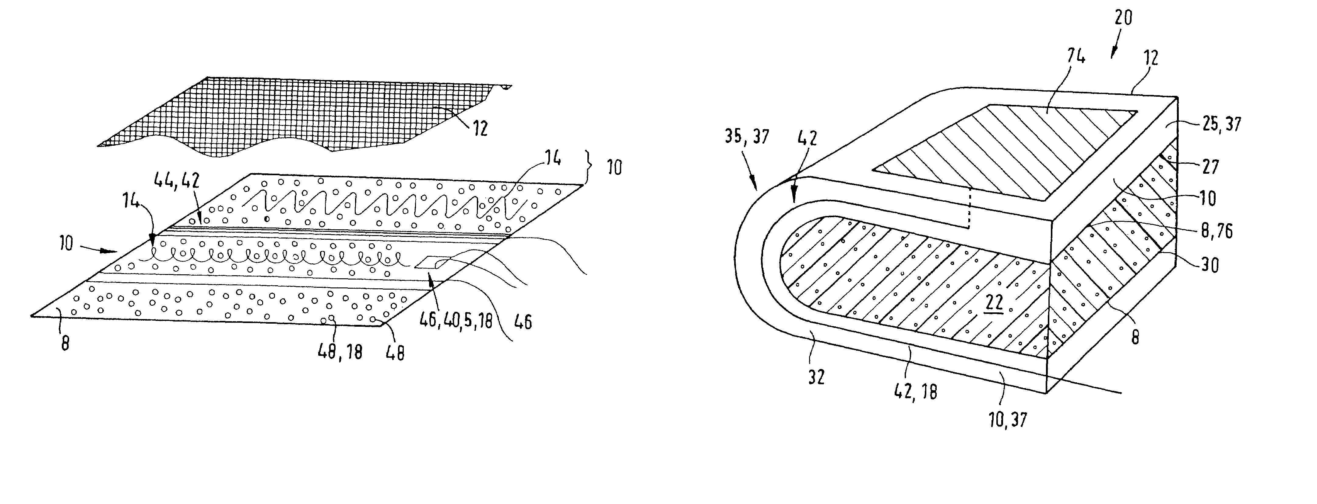
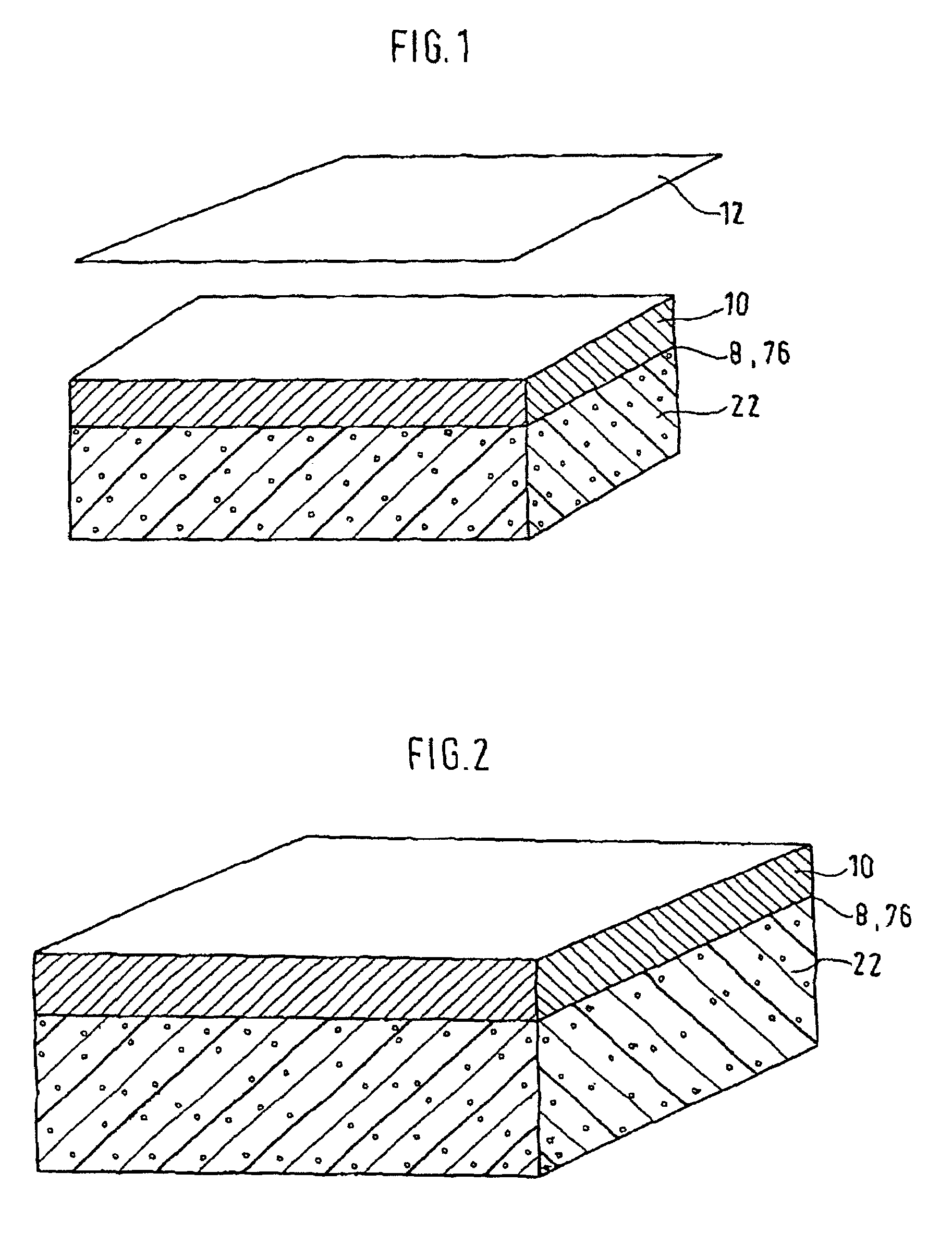
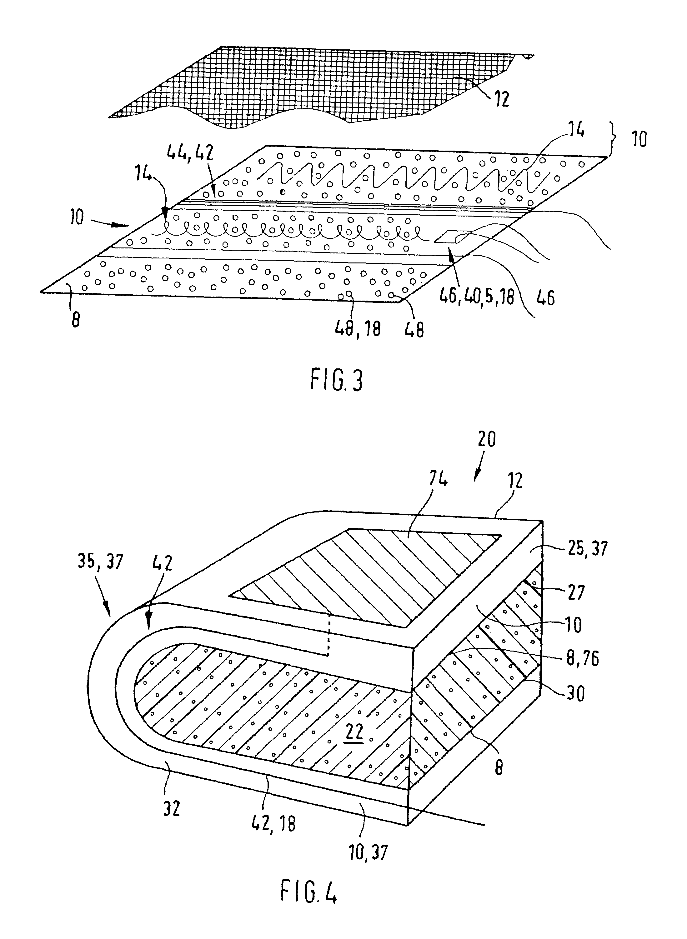
[0059]FIG. 1 shows the basic structure of a device according to the invention for accommodating functional elements in schematic, perspective view, using the example of a cushion. The cushion shown as the composite component comprises a bottom cushion core 22 and a base layer 8 placed thereon and joined to the cushion core, which base layer is preferably designed as a layer 76 that is impermeable to liquids. Located on the relatively thin base layer 8 is an intermediate layer 10 that is applied thereto and covered with a cover layer 12. The same situation, but without the cover layer 12, is shown once again in FIG. 2.

[0060]The cushion core 22 can be made, for example, of polyurethane foam (resilient polyurethane foam) or, for example, of rubberized hair. The intermediate layer 10 that functions as a distribution layer is composed of a spacer material which is characterized by high air permeability both transverse and perpendicular to the component surface. Air can flow through the i...


PUM


Abstract

A device (2) for accommodating functional elements in regions of a motor vehicle interior that are subjected to mechanical forces at least at times, having a base layer (8), an intermediate layer (10) and a cover layer (12), wherein the layers (8, 10, 12) are arranged so as to at least partially overlap one another, wherein the intermediate layer (10) has at least one support element (14) for the transmission of mechanical loads between the base layer (8) and cover layer (12), which element is made, in particular, of a firm but flexible material. In addition to the support element (14), additional functional elements (18) are arranged in the remaining space (16) between the base layer (8), the cover layer (12) and the support element (14).

Description

[0001]The present invention concerns a device for accommodating functional elements in regions of a vehicle interior that are subject, at least at times, to mechanical forces. The device includes a base layer, an intermediate layer and a cover layer. The layers are arranged so as to at least partially overlap one another. The intermediate layer has at least one support element for the transmission of mechanical loads between the base layer and cover layer. Such functional elements can be, in particular, cushion or trim elements of a motor vehicle interior and, more particularly, of a vehicle seat.BACKGROUND[0002]Known from U.S. Pat. No. 1,541,213 and from U.S. Pat. No. 2,922,466 are seat cushions in which a plurality of coils arranged next to one another in a single plane form a spacer layer between the seat and the user. This is intended to prevent excessive sweating on the part of the user. No actual control of moisture transport is provided herein.[0003]Known from U.S. Pat. No. 2...

Claims


Application Information

Patent Timeline
Patent Type & Authority Patents(United States)
IPC IPC(8): A47C7/72A47C7/02B60N2/56B60N2/70
CPCB60N2/5621B60N2/5685B60N2/7094B60N2/7017B60N2002/0264B60N2/0264
Inventor STOWE, STEFAN
Owner GENTHERM GMBH
Why Eureka
Try Eureka