
Sensor node

a node and sensor technology, applied in power management, instruments, liquid/fluent solid measurement, etc., can solve the problems of limited battery capacity, inability to use for a long time, small and light battery, etc., and achieve the effect of increasing the period of continuous usability

Active Publication Date: 2010-04-13
HITACHI LTD
View PDF16 Cites 4 Cited by
  • Summary
  • Abstract
  • Description
  • Claims
  • Application Information

AI Technical Summary

Benefits of technology

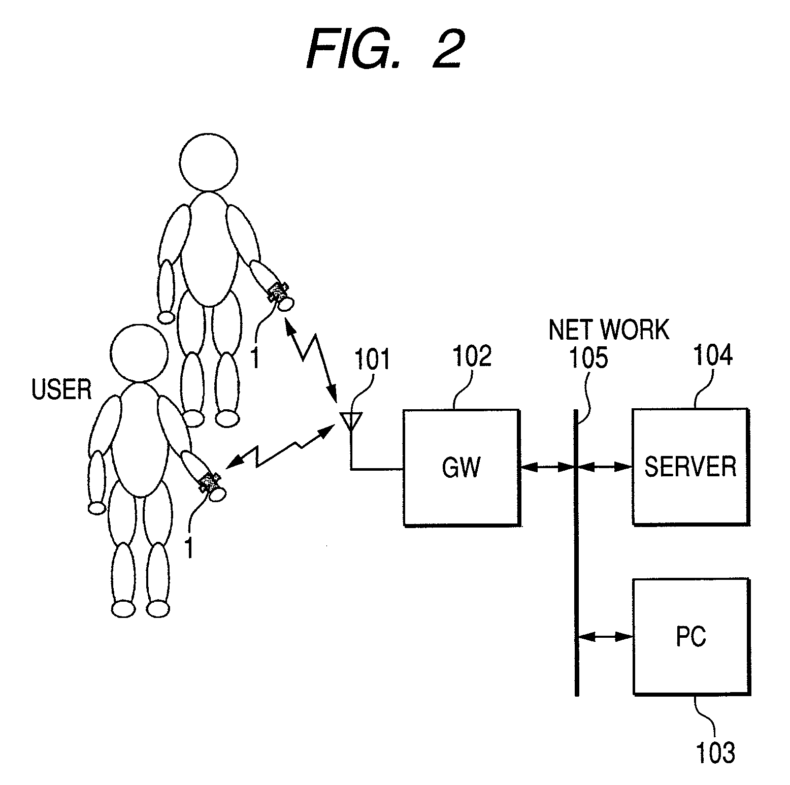
[0008]As a result, a possible solution is to set a short cycle of intermittent sensing and to monitor biological information almost continuously. Here, a sensor node for observing biological information can obtain almost at the real time the biological information of any moving living body provided that it includes a sensor, a radio communication unit for transmitting the information acquired by the sensor, and a CPU for controlling the sensor and the radio communication unit.
[0011]Accordingly, the present invention was made in view of the problem mentioned above, and the object is to increase the period of time wherein a sensor node for intermittently sensing with a short cycle can be continuously used while containing the consumption of battery.
[0014]Therefore, according to the present invention, during the measurement period the control unit acquires the information measured intermittently by the sensor (sensing data) by suspending the clock intermittently or lowering the clock frequency. By this mechanism, the control unit constituted by a microcomputer consuming much power and the like is limited to the minimum necessary operating time, and the sensor requiring much time for stabilization immediately after the supply of power is continuously supplied with power during the measurement period. Since the power consumption of a sensor is very small as compared with the power consumption of the control unit, the useless consumption of power can be avoided during the standby period of the control unit until stabilization when the sensor is switched “on” or “off.” In particular, even in the case of intermittent sensing with a short cycle, the consumption of battery can be contained and the period of continuous usability can be increased.

Problems solved by technology

On the other hand, since such a sensor node is worn personally on the living body of the user, the sensor node itself must be of a small and light construction, and the capacity of the battery is limited.
And it is not practical unless the cycle of battery replacement or charge is long to the maximum extent possible.
Thus, a small and light battery cannot stand any extended use, because power consumption becomes excessive.
And this constitutes a serious problem.
During this period of time, power is wasted.
In particular, as the radio communication unit consumes much power, in a system according to the JP-A No. 2005-329856 and the like, wasted power account for an important part of the power consumed by the radio communication unit.

Method used


Image

  • Sensor node
  • Sensor node
  • Sensor node

Examples


second embodiment

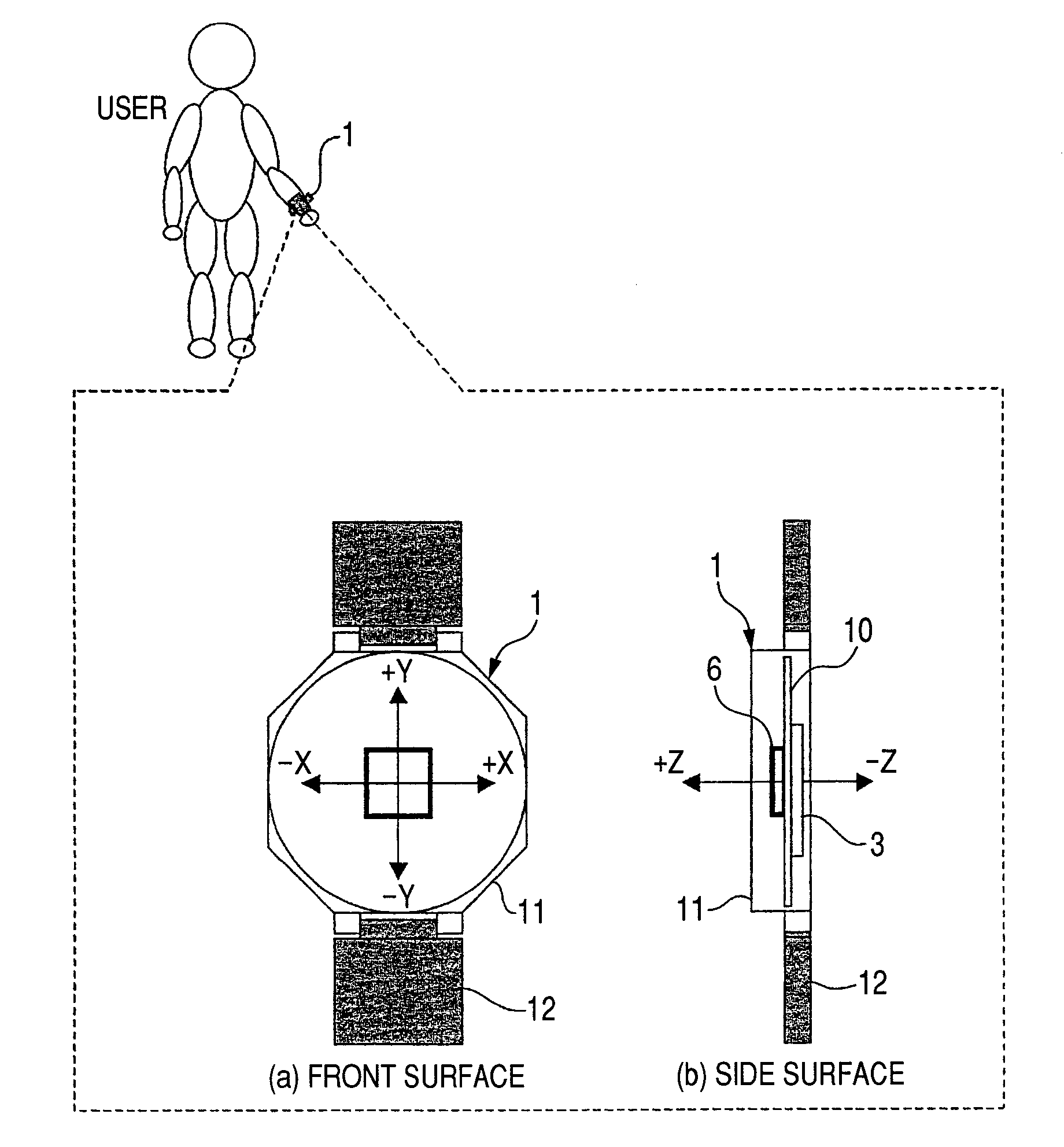
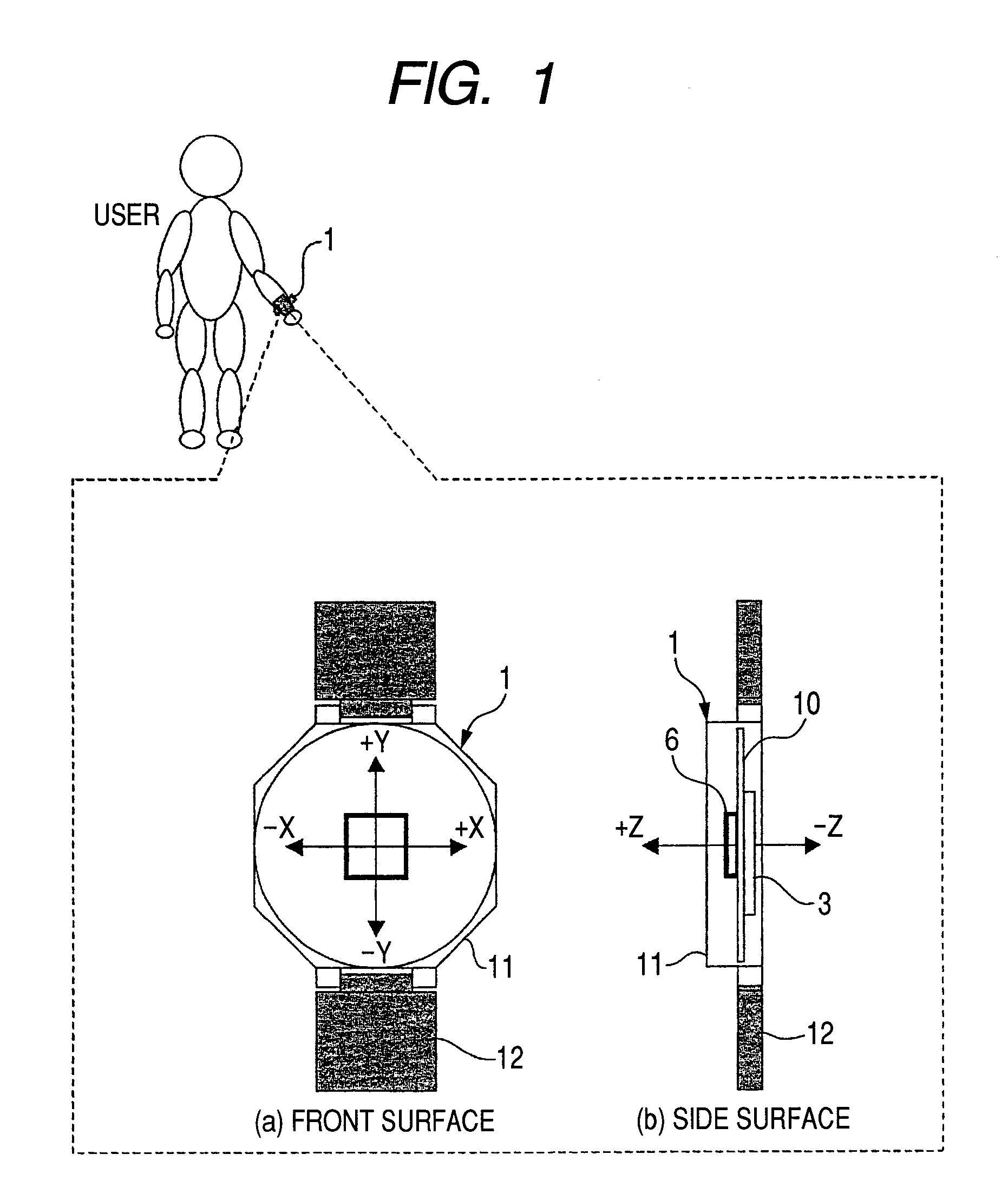
[0078]FIG. 9 shows the second embodiment, in which a pulse wave sensor 9 for measuring pulse waveform is added to the acceleration sensor 6 according to the first embodiment. It is identical to the first embodiment with respect to the other features.

[0079]On the backside of the case 11 of the sensor node 1, a pulse wave sensor 9 including a light-emitting element LD1 and a light-sensitive element PD1 is provided. This pulse wave sensor 9 uses an infrared light-emitting diode as the light-emitting element LD1, and adopts a phototransistor as the light-sensitive element PD1. Incidentally, a photodiode may be used in addition to the phototransistor as the light-sensitive element. On the backside of the case 11, the light-emitting element LD1 and the light-sensitive element PD1 are exposed, and can be facing with the arm skin.

[0080]This pulse sensor 9 irradiates subcutaneous blood vessels with infrared beams generated by the light-emitting element LD1, detects changes in the intensity o...

third embodiment

[0089]FIG. 13 shows partial modifications of the control shown in the first embodiment. In the step S11 shown in FIG. 5 of the first embodiment and #20 in FIG. 6, from the moment when the transmission frame is created until the end of the transmission by the radio communication unit 2, the clock of the microcomputer 3 is maintained at a constant value. In the third embodiment, on the other hand, after the start of the radio communication unit 2, the clock frequency of the CPU 34 is lowered, and other features are similar to the first embodiment.

[0090]In the step S11 described above, the CPU 34 of the microcomputer reads the sensing data (#1-#20) accumulated in the RAM 32 to create a transmission frame 670. And the created transmission frame 60 is transferred to the radio communication unit 2, which transmits the sensing data by radio communication.

[0091]When the created transmission frame 60 is transferred to the radio communication unit 2, the CPU 34 is charged with a low load of c...


PUM


Abstract

A sensor node for intermittently sensing data in a short cycle includes a control unit for acquiring information by driving the sensor, a radio communication unit for transmitting the information acquired by the control unit and a battery for supplying the control unit. The control unit includes a clock supply unit (RTC) for supplying the control unit with clocks at a predetermined frequency. A sensor control unit starts the supply of power to the sensor when the measurement period has begun, maintains the power supply to the sensor even if the control unit has shifted to the standby state during the measurement period, and shuts down the power supply to the sensor when the measurement period has been completed. A measurement unit is also provided for acquiring information from the sensor every time the latter has shifted to the operational state.

Description

CLAIM OF PRIORITY[0001]The present application claims priority from Japanese application JP 2006-232293 filed on Aug. 29, 2006, the content of which is hereby incorporated by reference into this application.FIELD OF THE INVENTION[0002]The present invention relates to improvements of a sensor node with radio communication function usable on a sensor net and in particular to a sensor node driven by a battery.BACKGROUND OF THE INVENTION[0003]In recent years, we have seen efforts to realize a network system (hereinafter referred to as “sensor net”) for bringing in various information of the actual world in real time into an information processing device by adding a small electronic circuit having a radio communication function to the sensor. A wide range of application is considered for the sensor net. For example, a proposal for its medical application is the use of a small electronic circuit integrating a radio communication circuit, a processor, a sensor and a battery to constantly m...

Claims


Application Information

Patent Timeline
Patent Type & Authority Patents(United States)
IPC IPC(8): G08B1/08G06F1/00G06F1/26G08B21/00H04W52/00H04W52/02H04W84/18H04W88/02
CPCH04W52/029H04W84/18H04W88/02
Inventor AIKI, KIYOSHIYAMASHITA, SHUNZOTANAKA, TAKESHI
Owner HITACHI LTD
Learn More