System, method, and program product for targeting and optimal driving force distribution in energy recovery systems

a technology of energy recovery system and optimal driving force, applied in the field of energy recovery system, can solve the problems of not being particularly flexible in application, chemical processes consume energy to provide desired, many different types of processes consume energy, etc., and achieve the effect of optimizing design, improving energy efficiency consumption, and efficient operation

Active Publication Date: 2010-04-13
SAUDI ARABIAN OIL CO
View PDF6 Cites 54 Cited by
  • Summary
  • Abstract
  • Description
  • Claims
  • Application Information

AI Technical Summary

Benefits of technology

[0019]In view of the foregoing, embodiments of the present invention advantageously provide an improved method, system and program product for theoretical, practical and economical energy targeting for the design and retrofit of energy recovery systems to find global energy utility targets, establish a good starting point for energy system design / retrofit using desired levels of heat recovery, find optimal driving force distributions in the energy system which is a function of the combined effect of process conditions and stream-specific minimum approach temperatures ΔTmini, and establish high fidelity relationship between energy cost versus capital cost to design energy recovery systems systematically and without enumeration.
[0021]The system can also include energy utility modeling program product either on a separate deliverable computer readable medium, e.g., DVD, etc., or stored in the memory of the energy utility modeling computer and adapted to optimize energy recovery for the process. The energy utility modeling program product can include instructions that when executed, for example, by the energy utility modeling computer, can cause the computer to perform the operations of receiving a plurality of sets of values each defining a potential range of attribute values for a separate one of a corresponding plurality of hot resource streams; one or more sets of a plurality of values each defining a potential range of attribute values for a separate one of a corresponding plurality of cold resource streams; and / or a plurality of sets of stream specific minimum temperature approach values ({ΔTmini}) assignable to the plurality of hot resource streams, with at least two of the values within each set being different from each other. The operations can also include determining a global heating energy utility interval ([Qh(minimum), Qh(maximum)]) and a global cooling energy utility interval ([Qc(minimum), Qc(maximum)]) responsive to the operations of receiving and assigning at least portions of the plurality of sets of stream specific minimum temperature approach values ({ΔTmini}) to the plurality of hot resource streams. Note, this calculation can be facilitated using a cascading algorithm.
[0028]Embodiments of an improved system, program product and method are provided which allow for flexibility in the ability of a user to input potential ranges of values or settings for the operational attributes of material streams within an industrial process. In an embodiment of the present invention, the improved system, program product and method also allows the calculation of the global minimum and maximum energy consumed for heating (Qh) and the global minimum and maximum energy consumed for cooling (Qc) for the process model at an optimal driving force distribution between the hot and the cold streams in the energy system systematically and without enumeration. An embodiment of the present invention also allows for defining the optimal driving force distribution that renders the global optimum of heating or cooling utility.
[0030]Embodiments of the present invention can have several commercial benefits. For example, embodiments of the present invention allow for application of a unique advanced methodology automated in a user-friendly program product to optimally design and efficiently operate process units and energy recovery system in industrial facilities. Industrial companies can improve energy efficiency consumption and pollution minimization points of view in designing and operating their facilities. An estimated 10% improvement in energy efficiency due to the application of embodiments of this invention, which represents optimization beyond what is currently available from the state-of-art tools and technology, can result in savings estimated in the tens of millions of dollars per year in energy consumption and project capital.

Problems solved by technology

Many different types of processes consume energy to obtain an output result, or to produce a required product or compound.
For example, chemical processes consume energy to provide a desired result.
Although such software provides useful tools, they are not particularly flexible in application, and do not address some of the above problems systematically.
This limitation becomes compounded and makes the existing software difficult to employ effectively in large-scale processes, which employ many material streams, where these material streams may have a number of operational attributes which can be modeled and adjusted.
Further, process stream changes not only may result in a reduction in energy utility, but also may bring a reduction in ΔTmin.
The problem is interlinked and multi-dimensional in that process changes and stream-specific ΔTmin selection are competing for optimal selection of utilities, optimal process conditions, and optimal energy recovery system synthesis.
Both methods fail to solve the problem of finding optimal driving force distribution, systematically, due to both optimal process conditions and optimal stream-specific ΔTmin in energy systems and without manual iteration.
Currently, there are no methods or program products that can handle the theoretical, practical, and economical energy targeting problems under variable driving force distribution to find optimal distribution without manual iterations (manual data entry-trial and error) and in a user-friendly manner.
Recognized by the inventors, however, is that in most industrial processes, it is at least inefficient, if not impractical, to require that all heat exchangers (and thus, all process streams and utilities) obey the same global minimum value for driving forces, since streams (and utilities) in general have very different heat transfer coefficients.
When considering retrofitting, the same problems exist with still no practical solution to simultaneously finding energy targets under all possible combinations of different process conditions, while using stream-specific minimum approach temperatures (ΔTmini).
These methods, however, are based upon heuristics and are iterative, lack systemization, and do not consider the possible changes in process conditions that can result in significant changes in the energy system driving force distribution.

Method used


Image

  • System, method, and program product for targeting and optimal driving force distribution in energy recovery systems
  • System, method, and program product for targeting and optimal driving force distribution in energy recovery systems
  • System, method, and program product for targeting and optimal driving force distribution in energy recovery systems

Examples


Embodiment Construction

[0046]The present invention will now be described more fully hereinafter with reference to the accompanying drawings, which illustrate embodiments of the invention. This invention may, however, be embodied in many different forms and should not be construed as limited to the illustrated embodiments set forth herein. Rather, these embodiments are provided so that this disclosure will be thorough and complete, and will fully convey the scope of the invention to those skilled in the art. Like numbers refer to like elements throughout. Prime notation, if used, indicates similar elements in alternative embodiments.

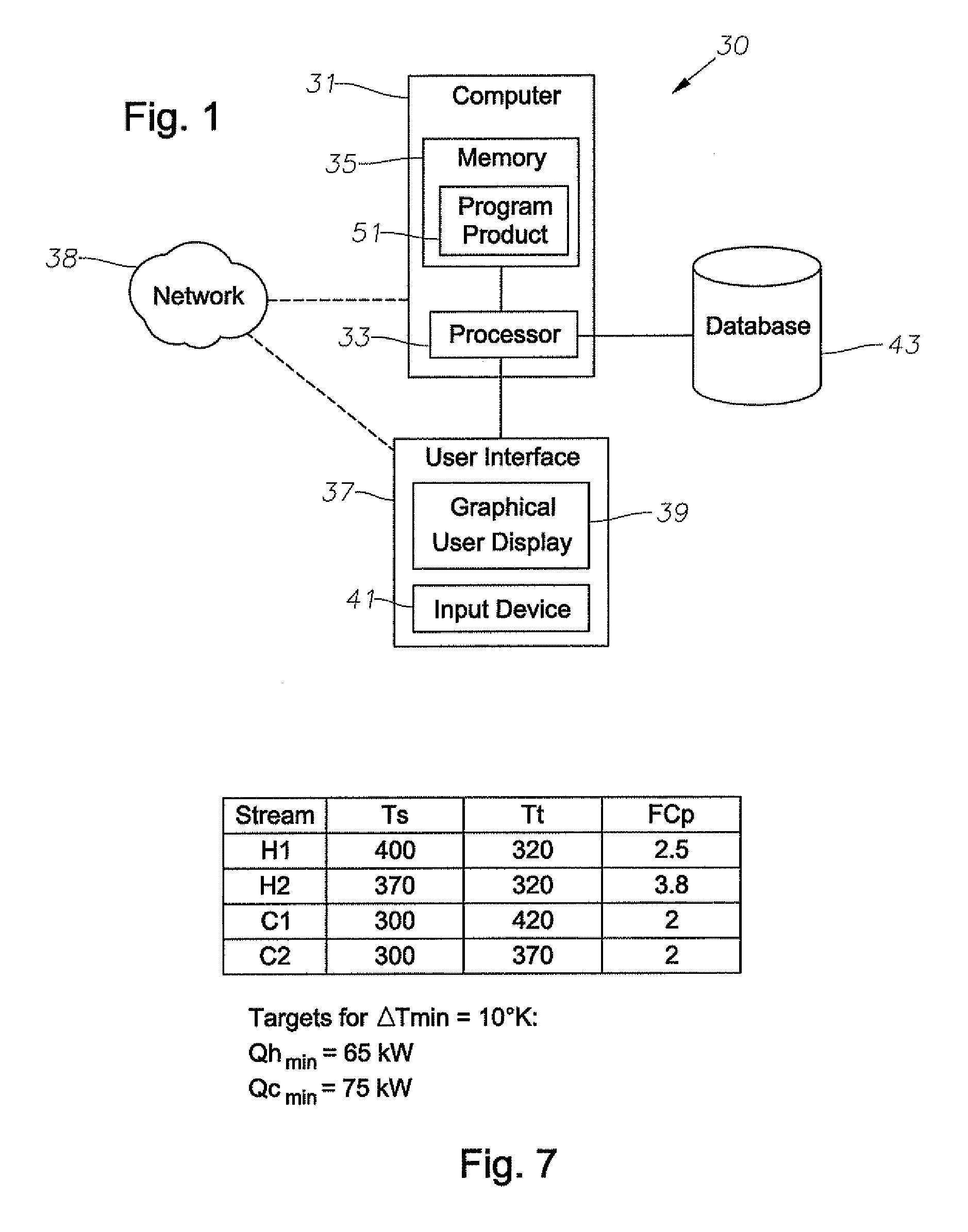
[0047]As shown in FIGS. 1-23, embodiments of the present invention provide a method, system and / or program product to be used to model the energy consumption of an industrial process to optimize heat / energy recovery within a process having a plurality of resource streams, through the determination of global energy utility targets and the determination of an optimal driving forc...


PUM


Abstract

A system, methods, and user-friendly program product to calculate global energy utility targets and define optimal driving force distribution for a process or cluster of processes under all possible process changes and streams specific minimum temperature approach values, simultaneously, and without enumeration, are provided. The program product can utilize stream-specific minimum temperature approach values ΔTmini, where the superscript i represents the specific hot stream, as the optimization parameters instead of the single global ΔTmin currently used, in addition to identifying the optimal operating conditions. The program product can define optimal process conditions and an optimal driving force distribution in heat recovery systems, and can produce an optimal Pareto-curve that shows the rigorous trade off between energy cost and capital cost for any energy recovery system.

Description

RELATED APPLICATIONS[0001]This non-provisional application claims priority to and the benefit of U.S. Patent Application No. 60 / 816,234 filed Jun. 23, 2006 incorporated herein by reference in its entirety.BACKGROUND OF THE INVENTION[0002]1. Field of the Invention[0003]This present invention relates to the field of energy recovery systems and related methods.[0004]2. Description of the Related Art[0005]Many different types of processes consume energy to obtain an output result, or to produce a required product or compound. For example, chemical processes consume energy to provide a desired result. For large scale processes which consume significant amounts of energy, it is preferable to minimize the energy consumed where possible. In the case of, for example, electrical energy generation systems or relatively large manufacturing plant or factories, it is preferable to optimize and potentially minimize the consumption of energy through careful operation, design or reconfiguration of t...

Claims


Application Information

Patent Timeline
Patent Type & Authority Patents(United States)
IPC IPC(8): G06F19/00G05D11/00G05D9/00
CPCF01K13/02G06Q10/067G05B13/021
Inventor NOURELDIN, MAHMOUD BAHYASEERI, AHMED SALEH
Owner SAUDI ARABIAN OIL CO
Why Eureka
Try Eureka