Techniques for distributing power in electronic circuits and computer systems

a technology of electronic circuit applied in the field of computer-aided analysis and design techniques, can solve the problems of large increase in power dissipation of microprocessors and computer systems, and achieve the effect of enhancing the thermal design of a system

Inactive Publication Date: 2010-04-13
GLOBALFOUNDRIES INC
View PDF15 Cites 16 Cited by
  • Summary
  • Abstract
  • Description
  • Claims
  • Application Information

AI Technical Summary

Problems solved by technology

This trend has resulted in a large increase in power dissipation for microprocessors and computer systems.

Method used


Image

  • Techniques for distributing power in electronic circuits and computer systems
  • Techniques for distributing power in electronic circuits and computer systems
  • Techniques for distributing power in electronic circuits and computer systems

Examples


Embodiment Construction

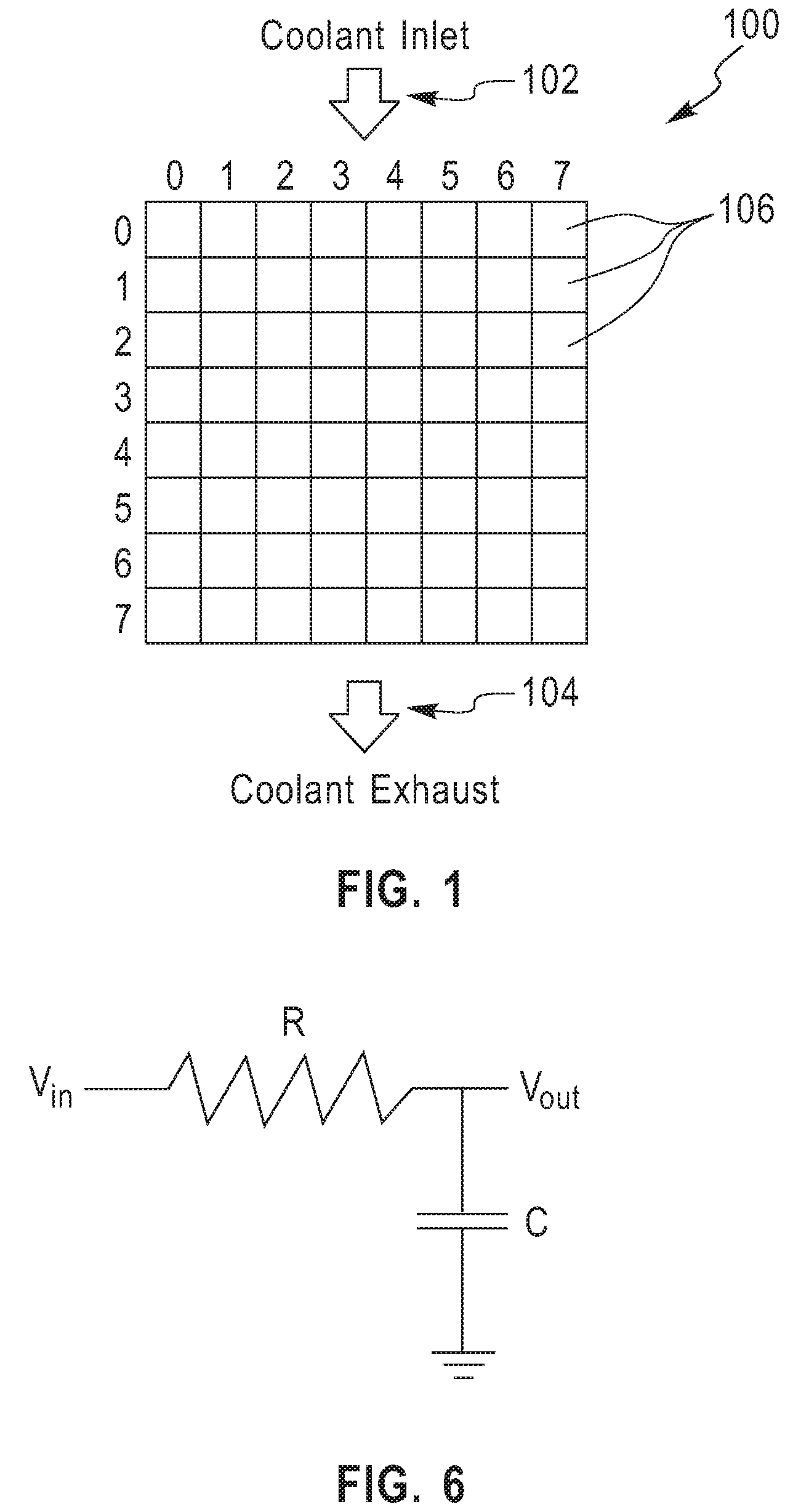
[0022]FIG. 1 shows a schematic diagram of a system 100 to which techniques of the present invention can be applied. System 100 can be representative, for example, of an integrated circuit chip, a computer system, or a data center. In the case of an integrated circuit chip, the system can be, for example, convectively cooled using a fluid coolant which is inlet at location 102 near the top of system 100 and exhausted at location 104 near the bottom of system 100. The configuration depicted is exemplary in nature, and techniques of the present invention can be applied to systems using different types of cooling, for example, free convection, forced convection (with different types of flow arrangements), radiation, conduction, and other known techniques. System 100 can be discretized into a number of smaller cells 106, such as elements (in the case of finite element analysis, e.g.) or nodes (in the case of finite difference analysis, e.g.). The fineness of this discretization is referr...


PUM

PropertyMeasurementUnit
temperatureaaaaaaaaaa
areaaaaaaaaaaa
areaaaaaaaaaaa

Abstract

Techniques for enhancing thermal design of a system having a number of boundary values are provided. A method for such enhancement includes representing thermal response of the system to the boundary values, obtaining at least one constraining parameter, and determining spatial and / or temporal distribution of the boundary values. The thermal response is represented as a superposition of temperature fields associated with given boundary values. The spatial and / or temporal distribution of the boundary values is determined based on the thermal response represented in the representing step, so as to satisfy the constraining parameter. The boundary values can be, for example, power sources, and the at least one constraining parameter can be, for example, a spatial or temporal location of one of the power sources.

Description

FIELD OF THE INVENTION[0001]The present invention generally relates to computer-aided analysis and design techniques, and, more particularly, to computer-aided analysis and design techniques pertinent to thermal design of electronic circuits, computer systems, and the like.BACKGROUND OF THE INVENTION[0002]The performance of electronic circuits, such as microprocessors, and that of computer systems has continued to increase. Such increasing performance has most often been obtained by aggressive scaling of individual devices, in turn allowing an increase in device density on the silicon circuitry. Additional functionality, cores and memory have also been added to typical circuits. This trend has resulted in a large increase in power dissipation for microprocessors and computer systems.[0003]As a result of the trend towards increased power, there has been an effort to reduce the power consumption of microprocessors and computer systems. Accordingly, a good deal of attention has recentl...

Claims


Application Information

Patent Timeline
Patent Type & Authority Patents(United States)
IPC IPC(8): G06G7/56G01J5/00G01K17/00G01K3/04G01K3/06G06G7/50
CPCG01K7/42G01K7/425G01K2215/00
Inventor HAMANN, HENDRIK F.LACEY, JAMES A.WAKIL, JAMILWEGER, ALAN J.
Owner GLOBALFOUNDRIES INC
Why Eureka
Try Eureka