Transport system for nanoparticles and method for the operation thereof

a technology of nanoparticles and transport systems, applied in the direction of diaphragm valves, operating means/release devices of valves, engine diaphragms, etc., can solve problems such as problems such as external feeding into pvd processes, and achieve the effect of low level of magnetization or charg

Inactive Publication Date: 2010-04-20
SIEMENS AG
View PDF20 Cites 2 Cited by
  • Summary
  • Abstract
  • Description
  • Claims
  • Application Information

AI Technical Summary

Benefits of technology

[0007]The transport system according to the invention for nanoparticles makes use of the effect that the nanoparticles can be moved even by small forces because their mass is very small, so that even a low level of magnetization or charge on the nanoparticles is sufficient for transportation in the transport system. This is because it has been found that nanoparticles exhibit a behavior when being transported which differs greatly from the behavior of conventional powder particles with particles sizes in the micrometer range. Because of their small particle size, nanoparticles in fact exhibit a behavior which is related to that of the individual charge carriers such as ions, when being transported.
[0010]According to one particular refinement, the transport system is characterized in that the inner wall of the transport channel can move radially with respect to its profile and is equipped with an actuator, in such a manner that the actuator can produce movements of the inner wall at right angles to the wall surface. This advantageously makes it possible to reduce or even suppress adhesion of nanoparticles to the inner wall of the transport channel. This simplifies the transport of the nanoparticles through the field generator, and, in particular, it is possible to prevent the transport channel from becoming blocked. In consequence, it is possible to also ensure transportation of nanoparticles in channels with very small diameters which are in the order of magnitude of three to five times the particle diameter of the nanoparticles. The actuator is particularly advantageously formed by a piezo-actuator which, for example, can cause the inner wall to oscillate in the ultrasound range.

Problems solved by technology

DE 196 32 393 A1 discloses that these so-called nanopowders cannot be poured without problems, so that, for example, external feeding into a PVD process is problematic.

Method used


Image

  • Transport system for nanoparticles and method for the operation thereof
  • Transport system for nanoparticles and method for the operation thereof
  • Transport system for nanoparticles and method for the operation thereof

Examples


Embodiment Construction

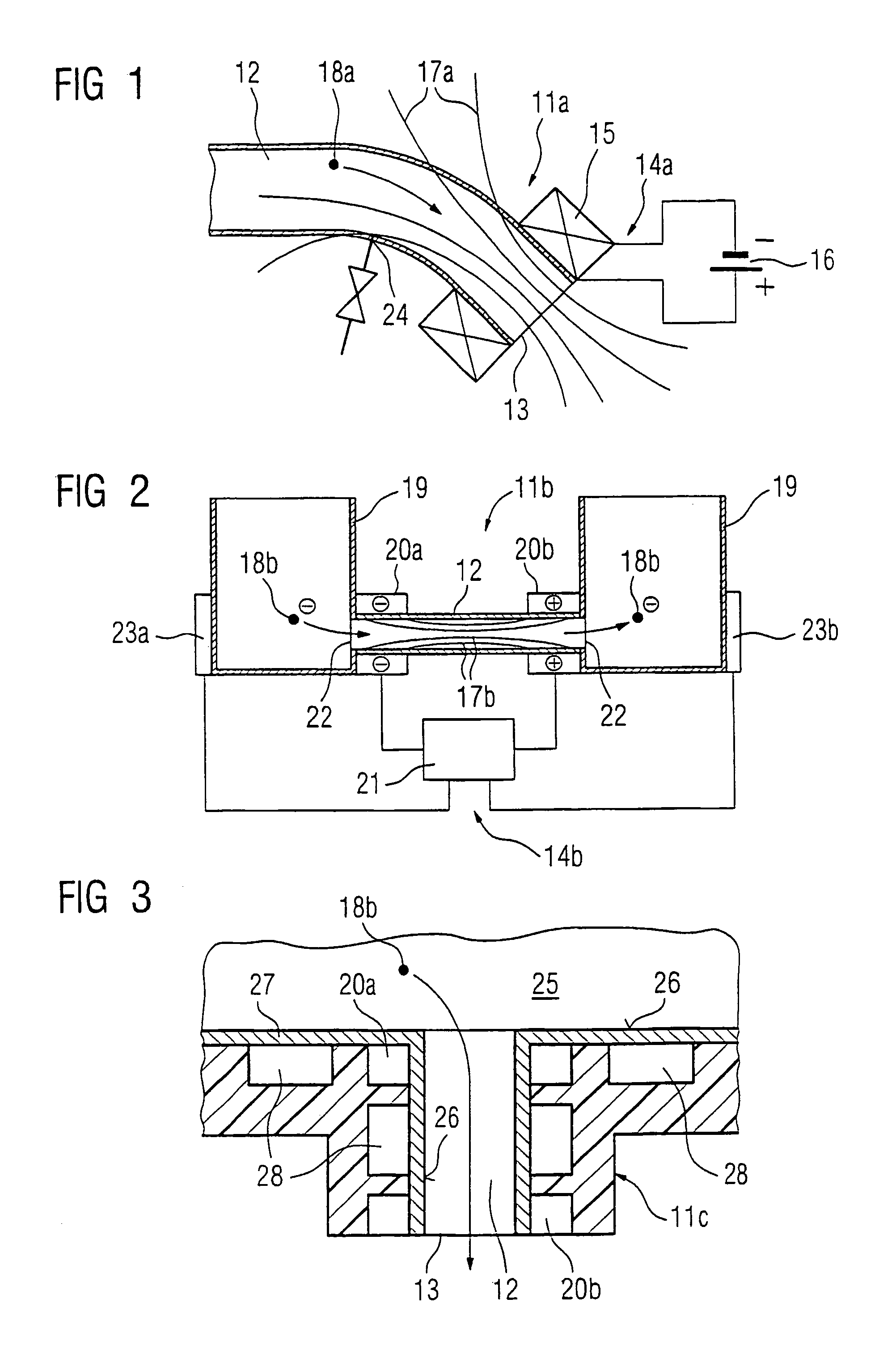
[0019]FIG. 1 illustrates a transport system 11a which has a transport channel 12 which ends in an ejection opening 13. A field generator 14a is also provided in the area of the ejection opening and comprises an electrical coil 15 and an electrical power supply 16. The coil 15 surrounds the transport channel 12 in an annular shape at the ejection opening 13, so that a homogenous magnetic field is created in the interior of the transport channel 12 in the area of the ejection opening 13 (indicated by magnetic lines of force 17a). The magnetic field which is formed in the rest of the illustrated profile of the transport channel 12 outside the coil 15 is in contrast inhomogeneous, with the magnetic induction decreasing as the distance from the coil increases.

[0020]The profile of the transport channel 12 essentially follows the profile of specific lines of force of the magnetic field which is produced, with the transport channel in this case being curved. Alternatively (not illustrated),...


PUM

PropertyMeasurementUnit
electric fieldaaaaaaaaaa
magnetic fieldaaaaaaaaaa
electrical fieldaaaaaaaaaa

Abstract

A transport system for dry nanoparticles (18b). According to the invention, the nanoparticles (18b) are magnetized or electrically charged for transportation, a magnetic or electrical field is produced by a field generator (20a, 20) in the transport channel, and the nanoparticles (18b) migrate through the transport channel (12). The nanoparticles can be discharged through a discharge opening (13) which enables dosing to take place. In order to agglomerate the nanoparticles (18b) or to prevent attachment onto the inner wall (26), a coating (27) of the wall can be offset in oscillations by piezo electric actuators (28), the oscillations being transferred to the nanoparticles (18b). The dry nanoparticles can be handled in an advantageous manner due to the transport system, such that the dry nanoparticles need not be treated as a suspension.

Description

FIELD OF THE INVENTION[0001]The invention relates to a transport system for nanoparticles.[0002]The expression dried nanoparticles is understood to mean very small particles with dimensions in the nanometer range, which are each composed of a large number of atoms or molecules. When these are dry, they form a nanodisperse powder, that is to say no liquid carrier medium is provided for transportation of the nanoparticles.BACKGROUND OF THE INVENTION[0003]DE 196 32 393 A1 discloses that these so-called nanopowders cannot be poured without problems, so that, for example, external feeding into a PVD process is problematic. Provision is therefore made for the powders not to be used as the source material for feeding into PVD processes but, in fact, for the nanoparticles to be produced in situ within the PVD process. For this purpose, suitable source substances must be fed into the PVD process (physical vapor deposition) for the nanoparticles to be produced.SUMMARY OF THE INVENTION[0004]Th...

Claims


Application Information

Patent Timeline
Patent Type & Authority Patents(United States)
IPC IPC(8): F15C1/04B65G54/02C23C14/24
CPCC23C14/246Y10T137/2191Y10T137/2082Y10T137/0391
Inventor JENSEN, JENS DAHLKRUGER, URSUSLUTHEN, VOLKMARSCHIEWE, HEIKE
Owner SIEMENS AG
Why Eureka
Try Eureka