
Vertical takeoff and landing aircraft using a redundant array of independent rotors

a technology of vertical takeoff and landing and independent rotors, applied in the field of aircraft, can solve the problems of increasing complexity, difficult operation of classic helicopters, and high degree of mechanical complexity of classic helicopter control systems, and achieve the effect of convenient operation and maintenan

Inactive Publication Date: 2010-04-20
HUGHEY ELECTRICOPTER CORP
View PDF27 Cites 74 Cited by
  • Summary
  • Abstract
  • Description
  • Claims
  • Application Information

AI Technical Summary

Benefits of technology

"The present invention is about a type of aircraft that can take off and land vertically. It uses multiple electric motors that are controlled individually to produce thrust. These motors are arranged in a way that if one of them fails, the aircraft can still stay in the air. This design ensures that the aircraft can still maintain flight even if one of the motors fails."

Problems solved by technology

However, there are several pronounced drawbacks to the classic helicopter that many inventors have attempted to mitigate.
Classic helicopters are much more difficult to operate as compared to conventional aircraft.
Classic helicopters require a high degree of mechanical complexity in their control systems.
This complexity increases cost, making classic helicopters significantly more expensive to manufacture than conventional fixed-wing aircraft.
This places considerable stresses on control linkages, which in turn, leads to high maintenance costs and failure potential.
This high blade mass also represents a greater impact energy hazard to ground personnel and structures during takeoff and landing.
Again, this makes classic helicopters very expensive to produce.
Because of this, critical parts tend to wear out relatively quickly.
This significantly increases the operating costs above that required for conventional aircraft
In short, the trade offs for the immense utility of the classic helicopter have been high procurement and maintenance costs, coupled with a very high skill level demand upon the pilot.
Many prior inventions attempt to mitigate high pilot skill requirements with higher drive unit mechanical complexity, leading to an increased failure probability and a higher cost.
Many prior inventions embody improper aerodynamic considerations, including rotor disk loading factors that are too high to be efficient or practical.
In the end, these manifestations of multiple articulating engine and / or lifting surfaces actually increase complexity and risk of catastrophic failure.
Some modest design variations on the classic helicopter configuration have enjoyed limited success, mainly due to elimination of the tail rotor component.
However, while some gains may have been made in reduction of piloting skill requirements, this came at the expense of multiplying the main rotor system complexity and associated costs.
The now famous NOTAR (VanHorn, U.S. Pat. No. 4,948,068) system eliminates the classic helicopter tail rotor by deflecting some downwash from the single main rotor (combined with turbine exhaust gasses), but this configuration still requires a much more complex mechanical control system than a conventional fixed-wing aircraft.
Virtually all other torque compensation systems require an additional thrusting power source directed laterally, increasing complexity and costs.
However, there have been scant few examples of multi-engine, multi-rotor helicopters in commercial use, and virtually none of those can remain in operation if one or more rotors fail.
For example, if a tilting drive unit failed to tilt properly, and at the appropriate time, a dangerously unstable flight condition would result.
There have been a few attempts to incorporate electrical control means to multi-rotor VTOL aircraft, but they have not been successful, mainly due to aerodynamic inefficiency.
Still, when compared to the rotor disk area of the ubiquitous Classic helicopter, this craft could not operate in hover in an efficient or fault-tolerant manner.
Also, the thrust units utilize a “tilt” feature that adds costly complexity, and represents an added hazardous point of failure.
This approach adds complexity and aerodynamic inefficiencies in another misguided attempt to combine fixed-wing aircraft attributes with standard helicopter maneuverability.
This adds unnecessary complexity and cost.

Method used


Image

  • Vertical takeoff and landing aircraft using a redundant array of independent rotors
  • Vertical takeoff and landing aircraft using a redundant array of independent rotors
  • Vertical takeoff and landing aircraft using a redundant array of independent rotors

Examples


Embodiment Construction

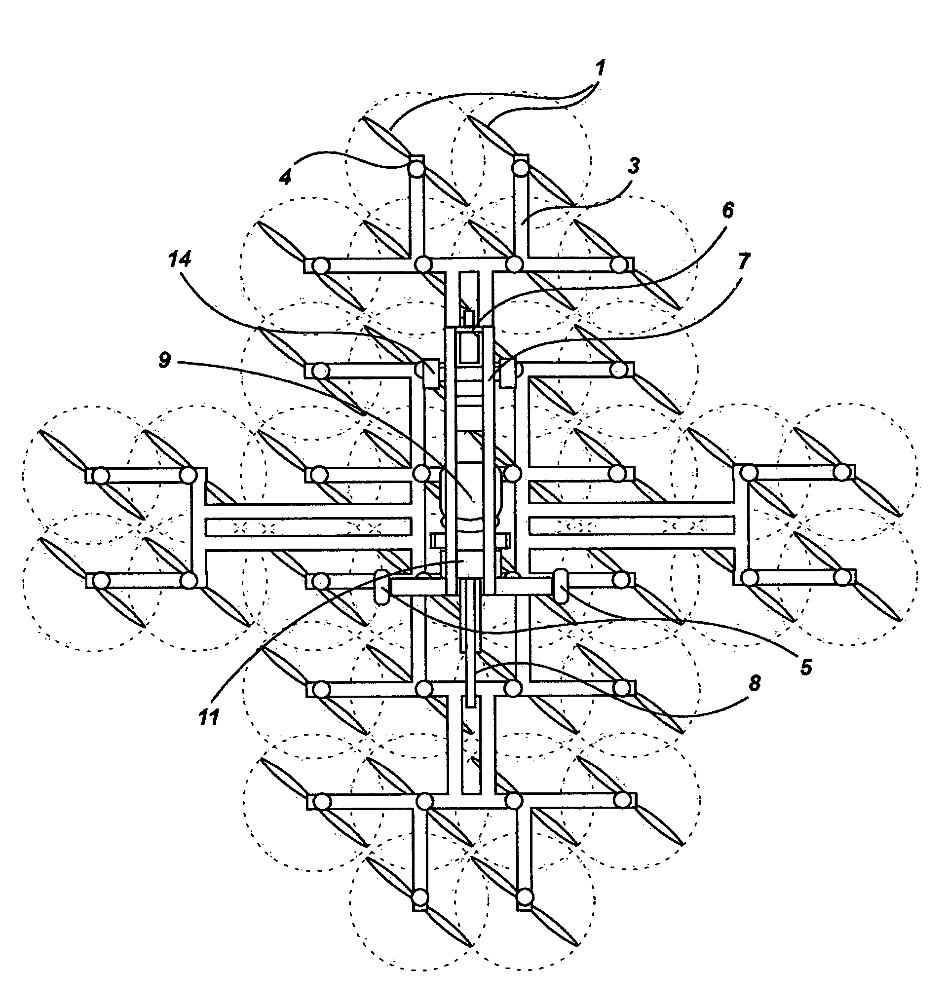
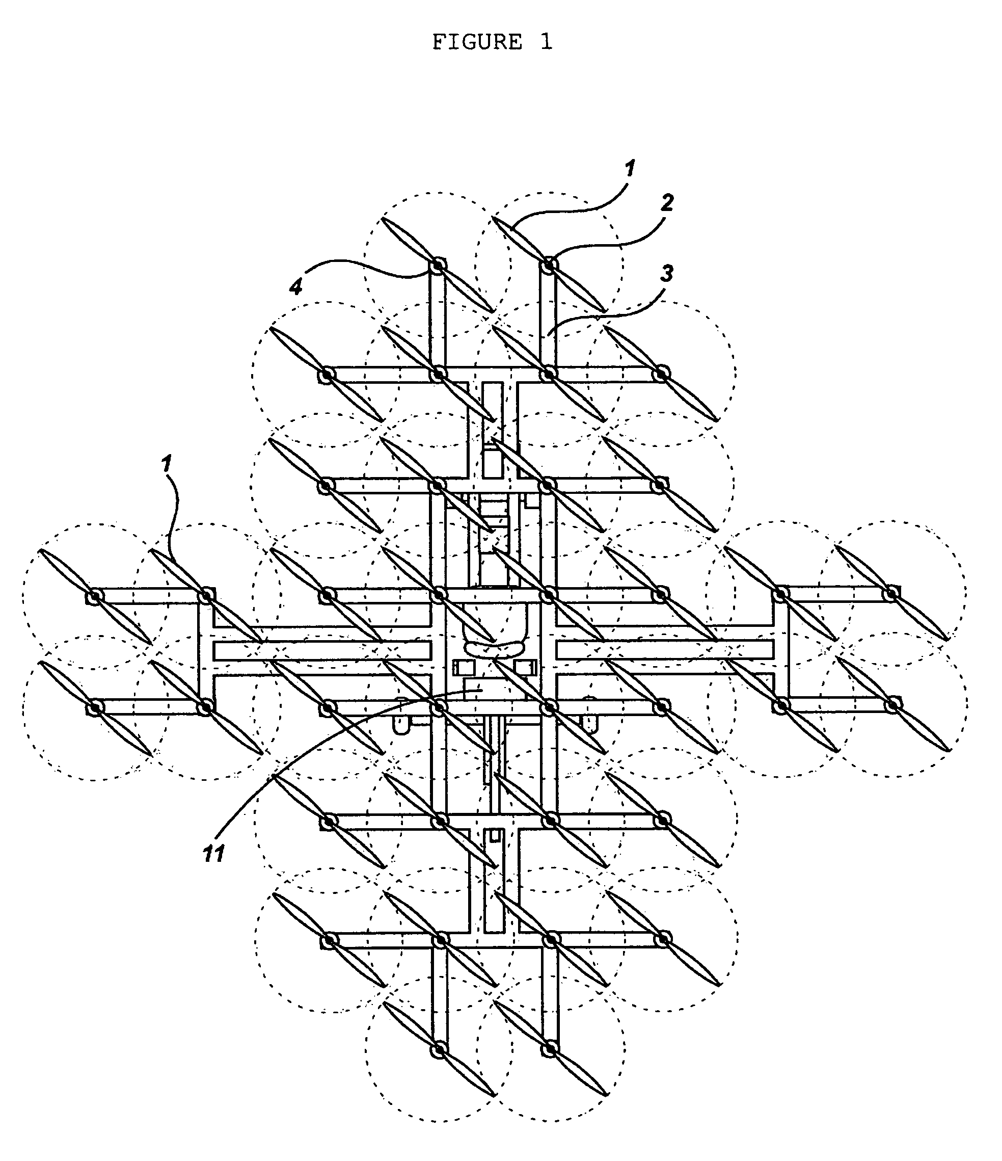
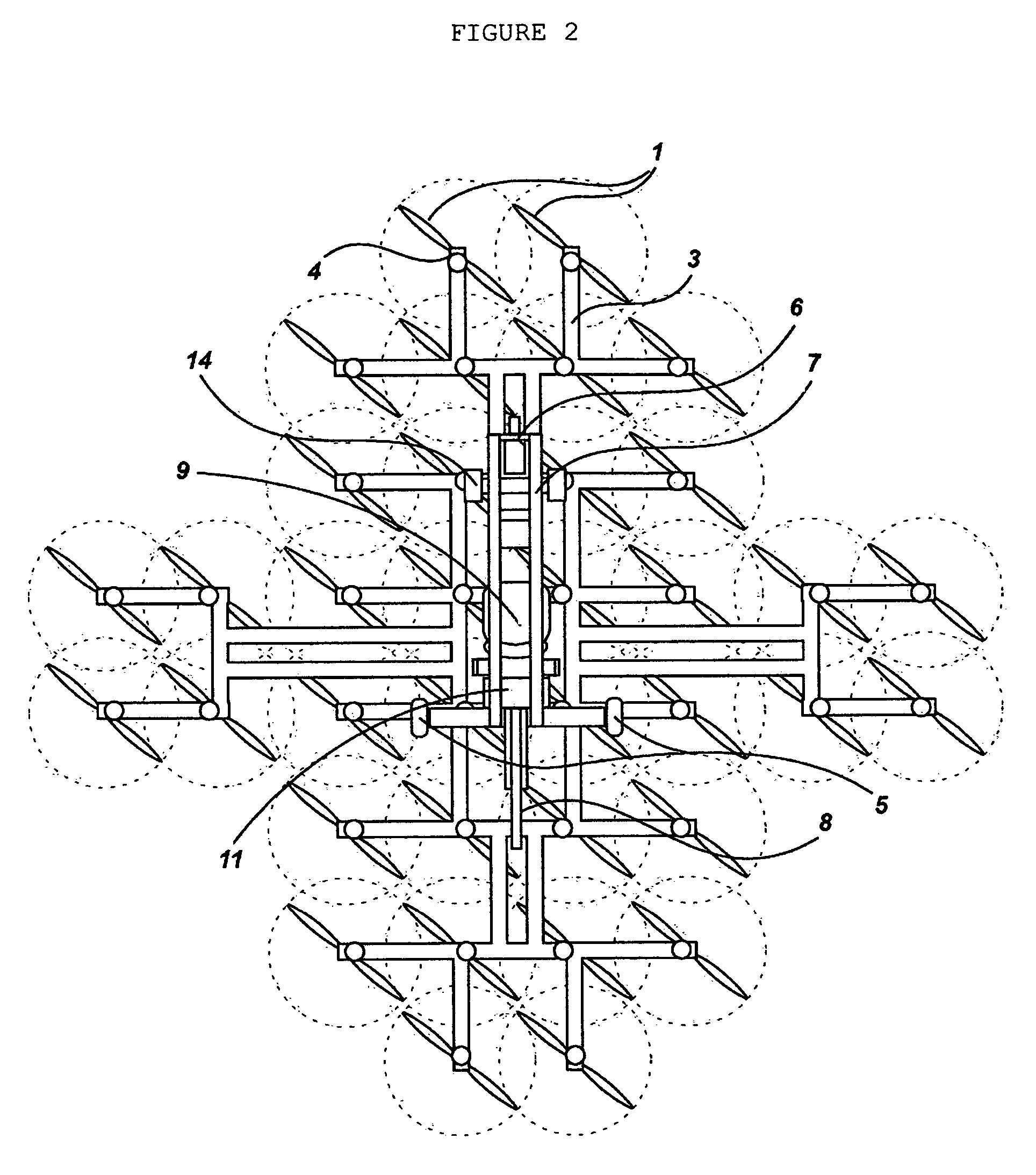
[0049]Anyone skilled in the art would agree that unless cyclic pitch were employed in a fixed rotor helicopter, a minimum of three lifting rotors would be required to allow simultaneous pitch and roll control. These three rotors would need to be arranged in an approximate equilateral triangle, with the center of gravity of the aircraft in general proximity to the center of the triangle. However, in this minimum configuration, the lack of appropriate thrust from just one rotor during flight would cause a catastrophic failure of the aircraft.

[0050]Therefore, a minimal embodiment of the present invention would include three redundant pairs, or 6 total thrust units arranged so that the failure of one thrust unit in a pair would allow the aircraft to continue operation.

[0051]The current embodiment employs 36 separate drive units for the Redundant Array of Independent Rotors (hereinafter “RAIR”). Any embodiment would incorporate a minimum of 6 units as 3 dual pairs, with a preferred embod...


PUM


Abstract

A vertical takeoff and landing aircraft, using for vertical lift and lateral thrust a redundant plurality of essentially similar electrically-powered and electronically-controlled thrust units mounted in a mechanically static or fixed fashion relative to one another in a substantially horizontal plane. The thrust units are situated in this planar array in aerodynamically approximate pairs, such that a complete failure of a single thrust unit would not substantially compromise the ability of the aircraft to maintain flight.

Description

CROSS REFERENCE TO RELATED APPLICATIONS[0001]The present application is a continuation application of U.S. provisional patent application Ser. No. 60 / 644,098, filed Jan. 14, 2005, for VERTICAL TAKE OFF AND LANDING AIRCRAFT USING A REDUNDANT ARRAY OF INDEPENDENT ROTORS, by Bradley Ward Hughey, included by reference herein and for which benefit of the priority date is hereby claimed.FIELD OF THE INVENTION[0002]The present invention relates to aircraft and, more particularly, to multiple rotor helicopters.BACKGROUND OF THE INVENTION[0003]Vertical Take Off and Landing (VTOL) aircraft have proven to be very useful transportation devices. In fact there are certain tasks, such as rough terrain rescue, where no other vehicle can approach the utility of a VTOL aircraft. If we are ever to realize the goal of universal personal aviation, easy-to-operate and inexpensive VTOL aircraft must be available.[0004]The most common VTOL aircraft today is the single main rotor helicopter, usually equippe...

Claims


Application Information

Patent Timeline
Patent Type & Authority Patents(United States)
IPC IPC(8): B64C27/08
CPCB64C31/028B64C27/08
Inventor HUGHEY, BRADLEY WARD
Owner HUGHEY ELECTRICOPTER CORP
Learn More