Multi-channel radar level gauge system

a radar level gauge and multi-channel technology, applied in the direction of using reradiation, liquid/fluent solid measurement, antennas, etc., can solve the problems of off-set error, large signal and measurement error of known systems, and relative complexity and cos

Active Publication Date: 2010-04-20
ROSEMOUNT TANK RADAR
View PDF21 Cites 25 Cited by
  • Summary
  • Abstract
  • Description
  • Claims
  • Application Information

AI Technical Summary

Benefits of technology

[0009]It is therefore an object of the present invention to provide an improved radar level gauging system which eliminate or at least alleviate the above-discussed problems of the prior art.
[0011]The transceiver circuitry and feeding circuitry of a particular channel are thus arranged on the same printed circuit board. The concentration of the feeding arrangement to PCBs enables better performance (insulation and matching) than known prior art solutions, and is relatively cost-effective and simple to produce. Thus, the collection of all critical microwave functions for each channel to one PCB is a very cost effective solution. Further, the present invention enables a very short microwave path from the TX / RX-modules to the antenna, which e.g. is an important property for good measuring performance at small distances.
[0015]At the same time, the present invention enables a very simple, cost-effective and reliable feeding for each channel. In particular, much lower VSWR (Voltage Standing Wave Ratio) and reduced off-set error levels are obtained, compared to the previously known systems using coaxial cables and turn-style junctions, and the inventive system may be used with essentially all frequencies conventionally used for RLG. Thus, the arrangement of the present invention provides a cost-efficient and effective solution for attaining the functional independence of the channels.
[0016]Further, since the accuracy of a radar system depends on a straight signal path without internal reflections, the system according to this aspect of the present invention also provides an improved accuracy. Hereby, offset errors and near-zone errors will be reduced.

Problems solved by technology

However, previously known systems of this type typically requires complex feedings arrangements, involving complex combiners, couplers and the like, and are therefore relatively complex and costly.
Further, these known systems are also impaired by relatively large signal and measurement errors.
The coaxial connectors have due to their design and specifications a rather high VSWR (Voltage Standing Wave Ratio) which introduces an off-set error which is difficult to predict, and in addition the coaxial cables introduce an internal length which will add near-zone errors.
Especially for frequencies where standard SMA (SubMiniature version A) connectors cannot be used, typically for frequencies above 18 GHz, the additional cost is also not negligible and the VSWR is bigger.

Method used


Image

  • Multi-channel radar level gauge system
  • Multi-channel radar level gauge system
  • Multi-channel radar level gauge system

Examples


Embodiment Construction

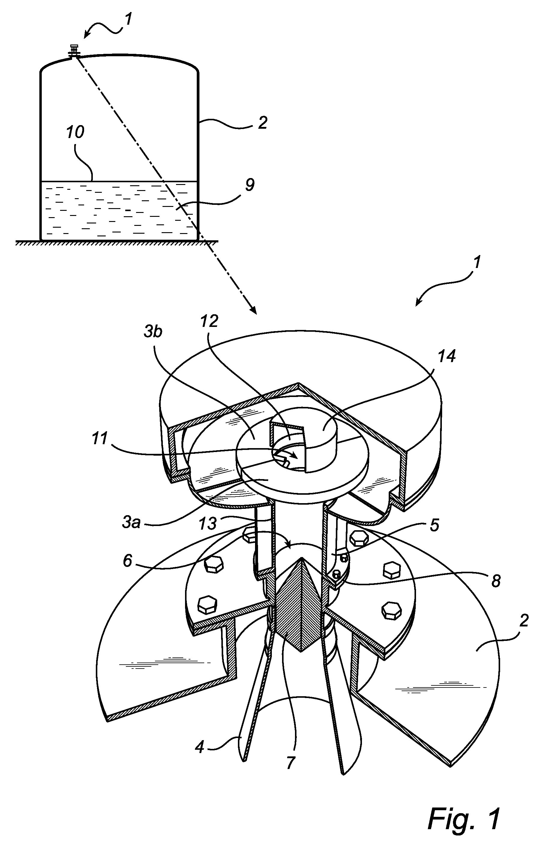
[0023]FIG. 1 shows schematically a radar level gauging system 1 according to an embodiment of the present invention, mounted to the roof of a tank 2.

[0024]In brief, the system in FIG. 1 is an exemplary radar level gauging system for determining a filling level L of a filling material 9 contained in the tank 2 by transmitting and receiving microwave signals over at least two separate and functionally independent channels, wherein the signals of the channels are distinguishable by a detectable characteristic for each channel. The filling material may be products such as oil, refined products, chemicals and liquid gas, or may be a solid material in powder or granular form, such as grain, pellets or coal. The tank 2 may be stationary or arranged on a moving vehicle, such as on a tanker.

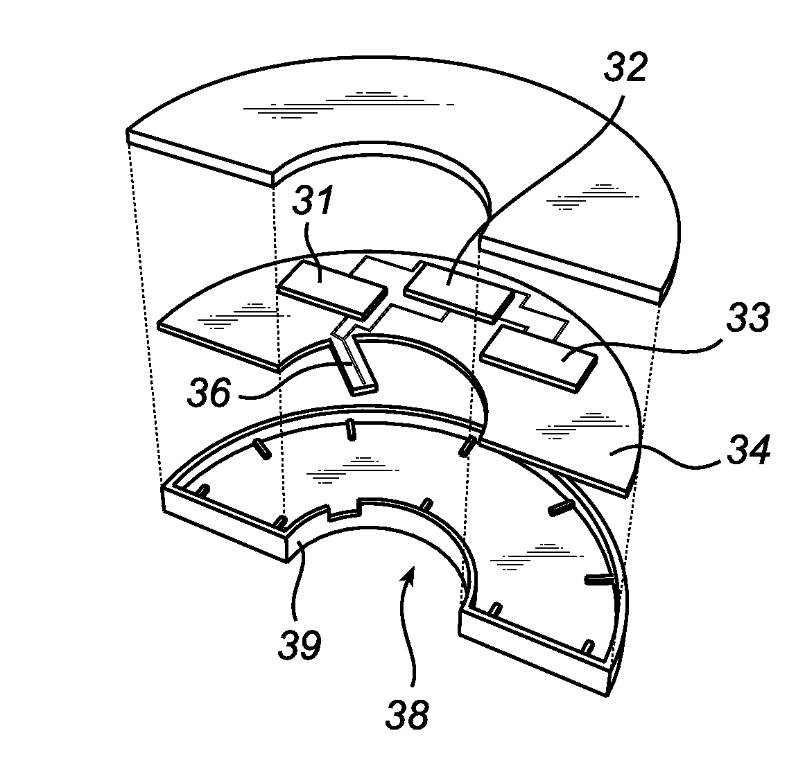
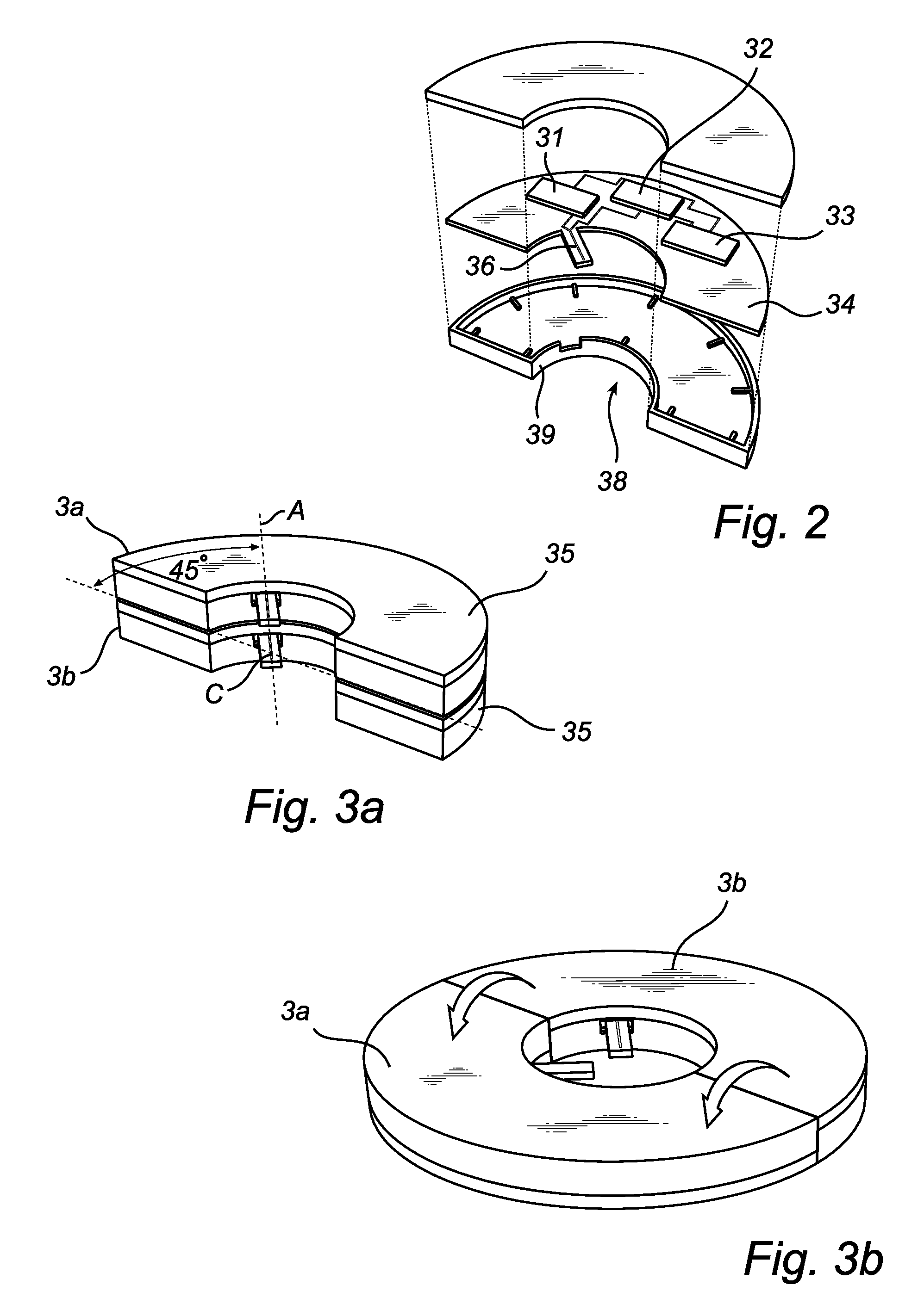
[0025]The radar level gauging system 1 comprises at least two electronics units 3a, 3b comprising transceiver circuitry 31, 32 (see FIG. 2) for transmitting and receiving radar signals in the at least two...


PUM


Abstract

A radar level gauging system for determining a filling level of a product contained in a tank by transmitting and receiving microwave signals over at least two functionally independent channels. Each channel has an electronics unit with transceiver circuitry arranged on a printed circuit board and processing circuitry connected to the transceiver circuitry for determining the filling level based on a relation between transmitted signals and received signals, and each electronics unit is electronically and galvanically separated from other electronics units. The system further comprises a single antenna for emitting microwave signals into the tank, and a hollow waveguide for guiding microwave signals between each transceiver circuitry and the antenna. Each electronics unit further comprises feeding circuitry arranged on the printed circuit board, the feeding circuitry comprising at least one feeding probe protruding into the waveguide for feeding the microwave signals into the waveguide.The present invention enables a very simple, cost-effective and reliable feeding for each channel.

Description

FIELD OF THE INVENTION[0001]The present invention relates to a radar level gauging system for determining a filling level of a filling material contained in a container by transmitting and receiving microwave signals over at least two separate and functionally independent channels, wherein the signals of said channels are distinguishable by a detectable characteristic for each channel, as well as to a corresponding method for determining such a filling level.BACKGROUND OF THE INVENTION[0002]Radar level gauging (RLG) to measure the level of a filling material, such as a liquid or a solid like a granulate is an increasingly important method for level gauging in tanks, containers, etc. Many different types of RLG systems are previously known. An example of such a systems is disclosed in U.S. Pat. No. 7,106,247 by the same applicant.[0003]For many applications, such as for instance in radar level gauging systems for a tanker's load containers, at least one overfill alarm that is functio...

Claims


Application Information

Patent Timeline
Patent Type & Authority Patents(United States)
IPC IPC(8): G01S13/08
CPCG01F23/284H01Q1/225G01S13/87G01S7/03
Inventor EDVARDSSON, OLOV
Owner ROSEMOUNT TANK RADAR
Why Eureka
Try Eureka