
Supporting a weak ordering memory model for a virtual physical address space that spans multiple nodes

a virtual physical address space and memory model technology, applied in the field of computers and virtual machines, can solve the problems of limiting the number of processors in an smp configuration, insufficient execution of programs with the desired performance, and ccnuma configuration may provide scalable performan

Inactive Publication Date: 2010-04-20
SYMANTEC OPERATING CORP
View PDF45 Cites 58 Cited by
  • Summary
  • Abstract
  • Description
  • Claims
  • Application Information

AI Technical Summary

Benefits of technology

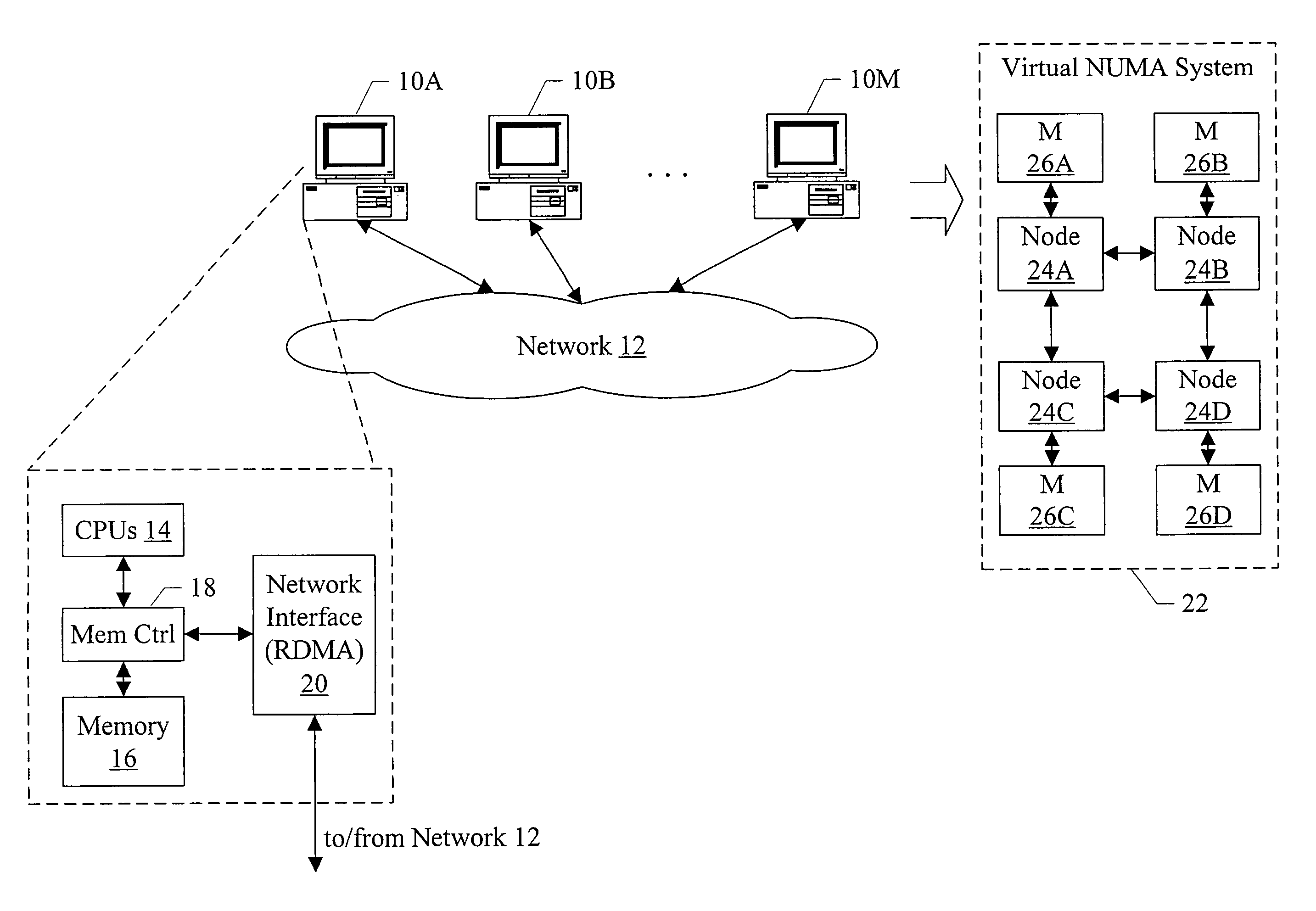
[0006]In one embodiment, a virtual NUMA system may be formed from multiple computer systems coupled to a network such as InfiniBand, Ethernet, etc. Each computer includes one or more software modules which present the resources of the computers as a virtual NUMA machine. The virtual NUMA machine comprises a plurality of nodes, each node having memory that is part of a distributed shared memory. Additionally, the virtual machine is coherent with a weakly ordered memory model. When executed in a current owner node of a first block in response to an ownership transfer request from a requesting node of the plurality of nodes for the first block, the software modules perform a synchronization operation if the first block has been modified in the current owner node.

Problems solved by technology

As the complexity and number of application programs for computers continues to grow, it is often the case that a computer employing a single processor (or central processing unit, CPU) is insufficient to execute the programs with the desired performance.
However, bandwidth limits and the physical limits on the size of a single memory system limit the number of processors in an SMP configuration that can effectively share the memory.
The ccNUMA configuration may provide scalable performance, but is often expensive due to the dedicated hardware and proprietary interconnect used in these systems.

Method used


Image

  • Supporting a weak ordering memory model for a virtual physical address space that spans multiple nodes
  • Supporting a weak ordering memory model for a virtual physical address space that spans multiple nodes
  • Supporting a weak ordering memory model for a virtual physical address space that spans multiple nodes

Examples


Embodiment Construction

[0025]Turning now to FIG. 1, a block diagram of one embodiment of a system comprising a plurality of computers 10A-10M coupled to a network 12 is shown. Generally, there may be any number of two or more computers 10A-10M in various embodiments. Each computer may comprise any computing device that is capable of independent program execution using the hardware and software resources within the computer device. For example, a computer may be physically housed in a computer housing (e.g. a personal computer (PC) in a desktop form factor or laptop form factor, a workstation, a server, a server in a rack mount, etc.). A computer may be one of the blades in a blade server. The network 12 may be any computer interconnection. For example, the network 12 may be compatible with the InfiniBand specification. Alternatively, the network 12 may be compatible with Ethernet, Gigabit Ethernet, 10 Gigabit Ethernet, or any other network (local area, wide area, etc.).

[0026]As will be discussed in more d...


PUM


Abstract

In one embodiment, a virtual NUMA system may be formed from multiple computer systems coupled to a network such as InfiniBand, Ethernet, etc. Each computer includes one or more software modules which present the resources of the computers as a virtual NUMA machine. The virtual machine is a non-uniform memory access (NUMA) machine comprising a plurality of nodes, each node having memory that is part of a distributed shared memory. Additionally, the virtual machine is coherent with a weakly ordered memory model. When executed in a current owner node of a first block in response to an ownership transfer request from a requesting node of the plurality of nodes for the first block, the software modules perform a synchronization operation if the first block has been modified in the current owner node.

Description

[0001]This application is a continuation-in-part of U.S. patent application Ser. No. 11 / 340,102, filed on Jan. 26, 2006. This application is a continuation-in-part of U.S. patent application Ser. No. 11 / 340,227, filed on Jan. 26, 2006.BACKGROUND[0002]1. Field of the Invention[0003]This invention is related to computers and virtual machines used with computers.[0004]2. Description of the Related Art[0005]Computers have become a ubiquitous part of modern society, and users have employed them for numerous demanding and often critical tasks. As the complexity and number of application programs for computers continues to grow, it is often the case that a computer employing a single processor (or central processing unit, CPU) is insufficient to execute the programs with the desired performance. Some computers implement multiple processors in a symmetric multiprocessing (SMP) configuration, sharing a common memory. However, bandwidth limits and the physical limits on the size of a single m...

Claims


Application Information

Patent Timeline
Patent Type & Authority Patents(United States)
IPC IPC(8): G06F15/167G06F12/00
CPCG06F12/0284G06F12/0815G06F2212/2542G06F2212/151G06F12/109G06F12/1036
Inventor WONG, KAI C.
Owner SYMANTEC OPERATING CORP
Learn More