Duty cycle correction circuit with small duty error and wide frequency range

Active Publication Date: 2010-04-27
NAT SEMICON CORP
View PDF4 Cites 20 Cited by
  • Summary
  • Abstract
  • Description
  • Claims
  • Application Information

AI Technical Summary

Problems solved by technology

Any error in the duty cycle requires more opamp bandwidth to settle to the same accuracy and therefore, more power consumption is needed.
The typical clock circu

Method used


Image

  • Duty cycle correction circuit with small duty error and wide frequency range
  • Duty cycle correction circuit with small duty error and wide frequency range
  • Duty cycle correction circuit with small duty error and wide frequency range

Examples


Embodiment Construction

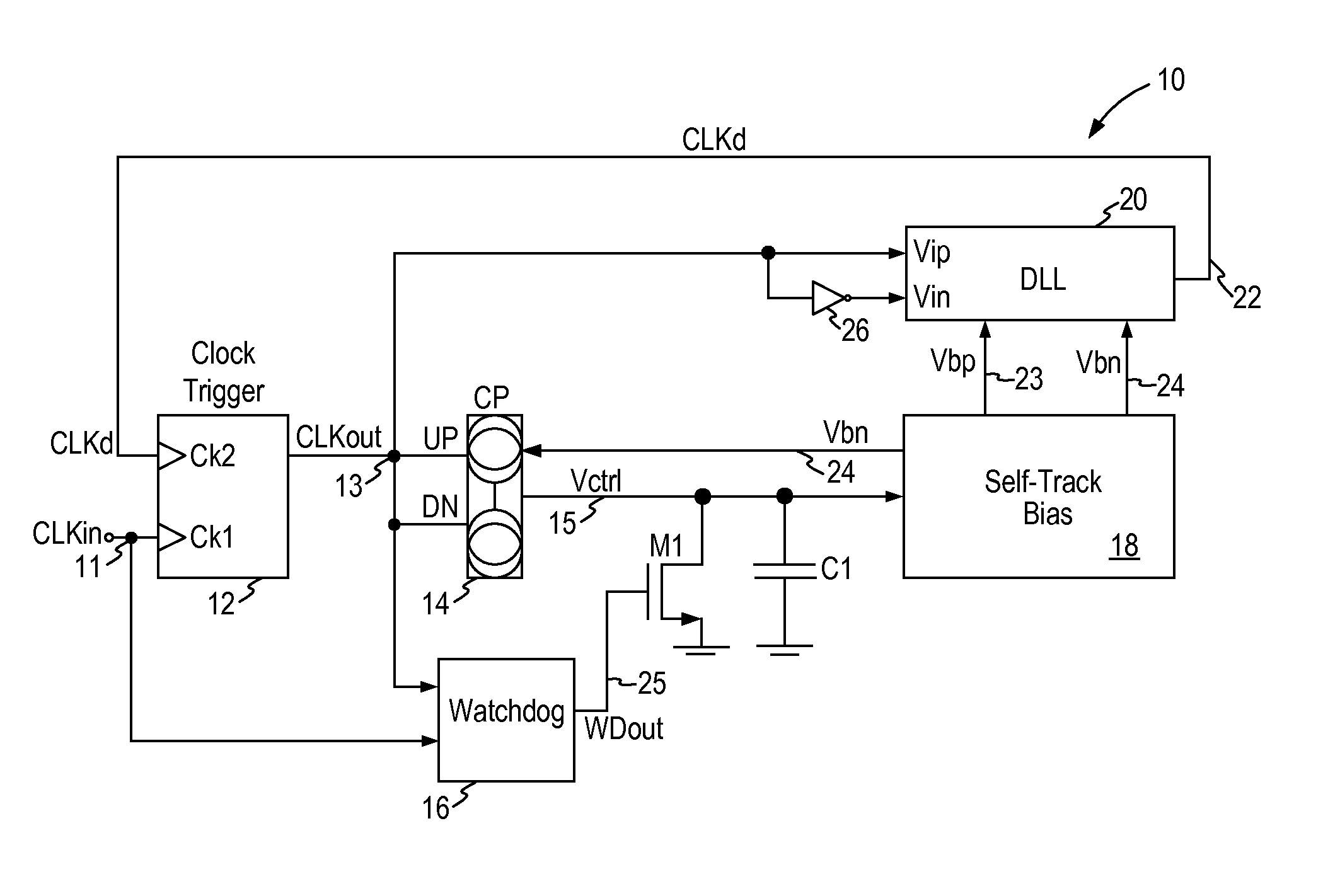
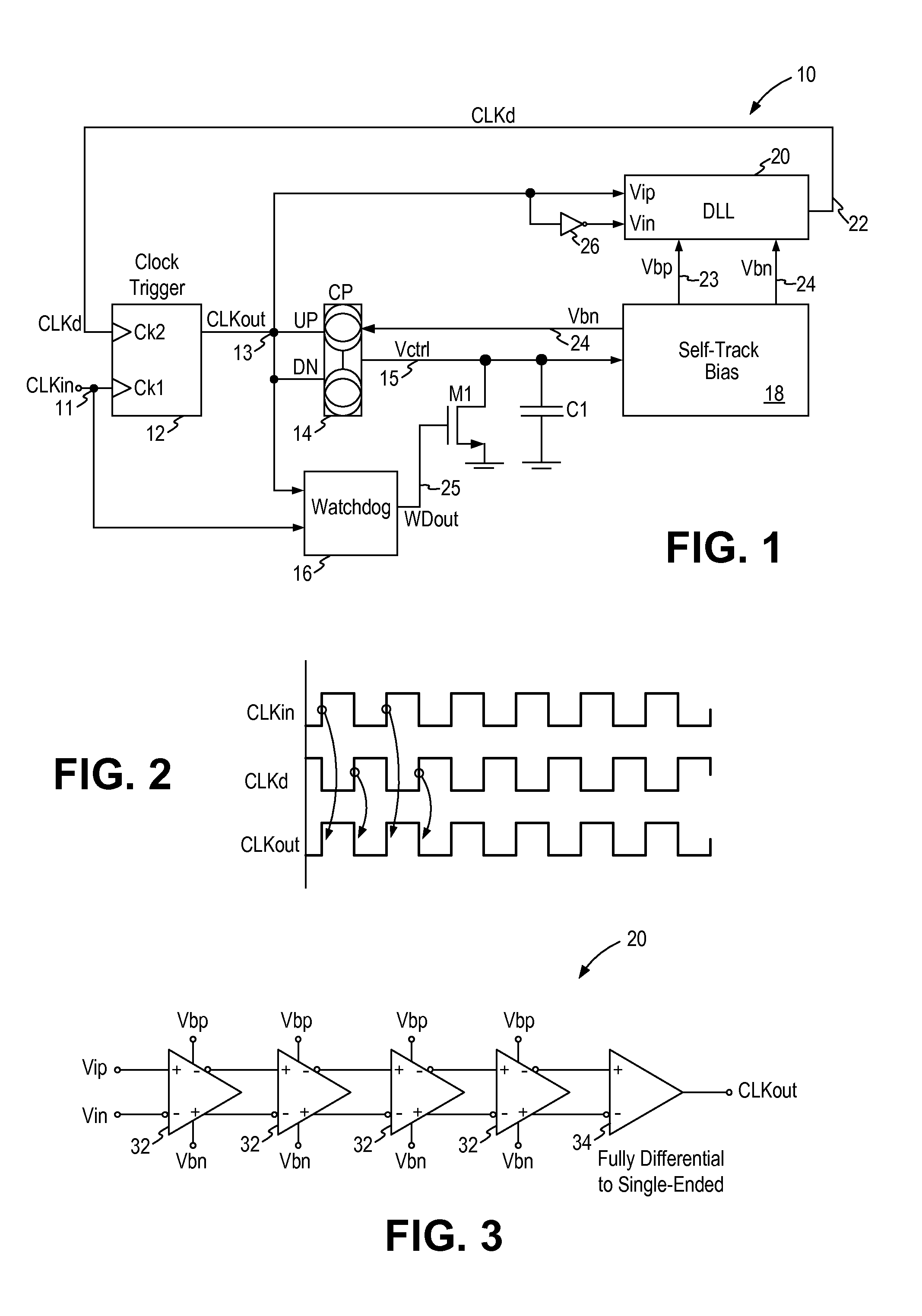
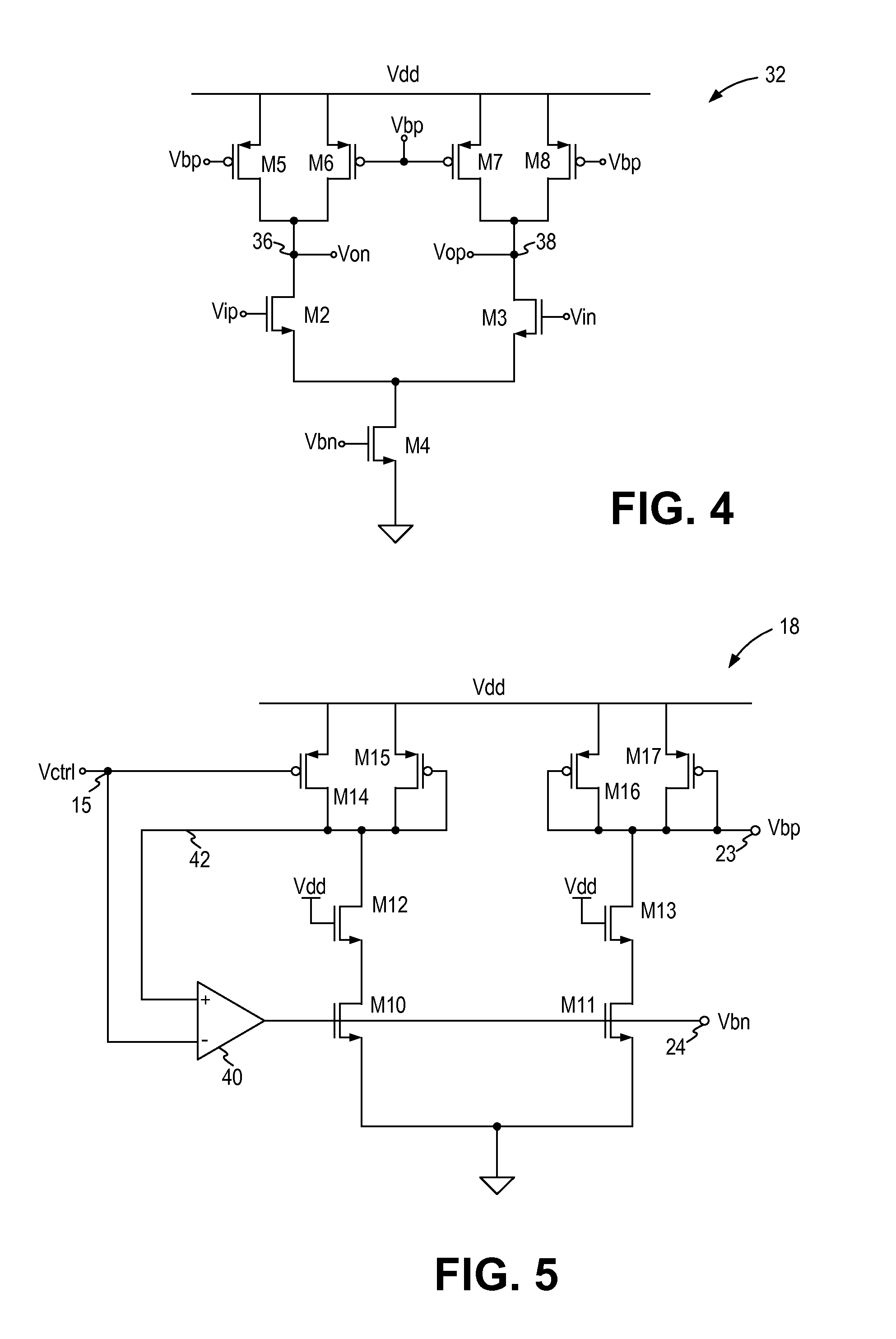
[0012]In accordance with the principles of the present invention, a duty cycle correction circuit incorporates a self-biased delay-locked loop (DLL) and a current-matching charge pump to achieve small duty cycle error over a wide frequency range. The self-biased DLL is biased by biasing voltages that tracks the temperature and process variations of the circuit instead of by fixed voltages. The charge pump generates charging and discharging currents that are well matched and are compensated for output impedance changes when the control voltage varies widely. Consequently, the duty cycle error of the duty cycle correction circuit can be made small over a wide input frequency range. In one embodiment, a watch dog circuit is provided to ensure proper startup and prevent false locking for input clock frequency that changes over a wide range.

[0013]The duty cycle correction circuit of the present invention operates without adding significant clock jitter to the output clock. Any jitter on ...


PUM


Abstract

A duty cycle correction circuit (10) for receiving an input clock signal (11) and generating an output clock signal (13) having a predetermined duty cycle includes a clock trigger circuit (12) generating the output clock signal (13) having a first clock edge triggered from the input clock signal and a second clock edge triggered from a delayed clock signal (22); a charge pump circuit (14) receiving the output clock signal and generating charging and discharging currents for a capacitor (C1) where a control voltage develops on the capacitor indicative of the duty cycle error of the output clock signal; a self-track bias circuit (18) receiving the control voltage and generating first and second bias voltages (23, 24) in response to the control voltage; and a delay-locked loop circuit (20) receiving the output clock signal and the first and second bias voltages and generating the delayed clock signal.

Description

FIELD OF THE INVENTION[0001]The invention relates to duty cycle correction circuit and, in particular, to a duty cycle correction circuit that operates with small duty error and over a wide frequency range.DESCRIPTION OF THE RELATED ART[0002]A conventional switched-capacitor pipeline analog-to-digital conversion (ADC) system includes multiple consecutive stages, each containing a switched-capacitor sample-and-hold (SAH) circuit, an analog-to-digital converter (ADC) and a multiplying digital to analog converter (MDAC). In switched-capacitor pipeline analog-to-digital conversion (ADC) system, the clock duty cycle plays a very important role to the accuracy of the data conversion. In most systems, a duty cycle of 50% is used. Pipeline ADC systems use both the rising and the falling clock edges for sampling and holding operation.[0003]Assume the clock period is “Ts” and duty cycle is “D”, then D*Ts is the time for one stage of the MDAC operational amplifier (opamp) to settle to the resi...

Claims


Application Information

Patent Timeline
IPC IPC(8): H03K3/017
CPCH03K5/1565H03L7/093H03L7/0812H03L7/0891H03K2005/00097H03K2005/00208
Inventor YU, HAOCHIN, SING W.WONG, BILL C.
Owner NAT SEMICON CORP
Why Eureka
Try Eureka