Filler circuit cell

a circuit cell and filter circuit technology, applied in the field of filter circuit cells, can solve problems such as the inability to achieve a perfect rectangle and the breakdown of the entire transistor

Active Publication Date: 2010-04-27
UNITED MICROELECTRONICS CORP
View PDF2 Cites 89 Cited by
  • Summary
  • Abstract
  • Description
  • Claims
  • Application Information

AI Technical Summary

Problems solved by technology

In most cases, numerous gaps are found in each cell unit as a perfect rectangle is impossible to achieve.
This results in breakdown of the entire transistor.

Method used


Image

  • Filler circuit cell
  • Filler circuit cell
  • Filler circuit cell

Examples


Embodiment Construction

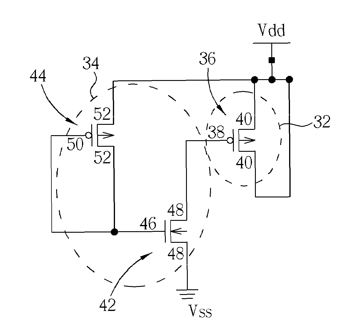
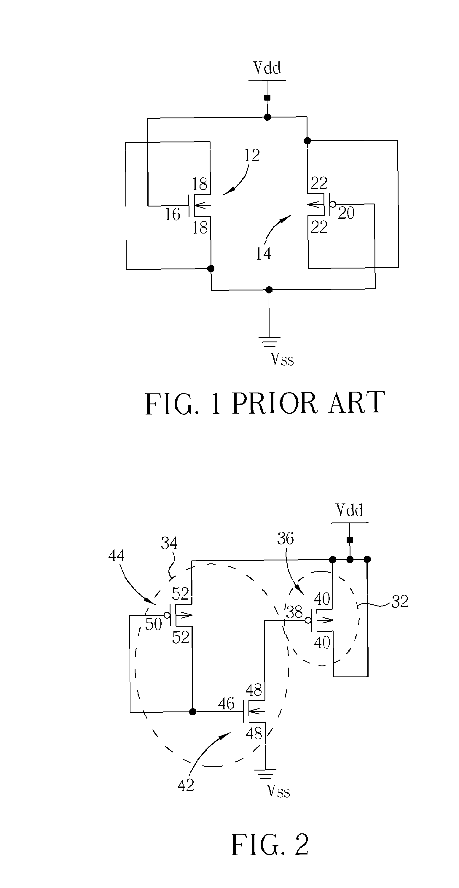
[0016]Referring to FIG. 2, FIG. 2 illustrates circuit diagram of a filler circuit cell according to a preferred embodiment of the present invention. The filler circuit cell preferably includes a decoupled capacitor 32 and a voltage stabilizing unit 34 connected to the decoupled capacitor 32. The decoupled capacitor 32 includes a transistor, such as a PMOS transistor 36. The PMOS transistor 36 includes a gate 38, a source 40 and a drain 40. The voltage stabilizing unit 34 includes a NMOS transistor 42 and a PMOS transistor 44, in which the NMOS transistor 42 includes a gate 46, a source 48 and a drain 48 and the PMOS transistor 44 includes a gate 50, a source 52 and a drain 52.

[0017]In this embodiment, one source / drain 52 of the PMOS transistor 44 of the voltage stabilizing unit 34 is directly connected to a voltage source Vdd while the gate 50 and the other source / drain 52 is connected to the gate 46 of the NMOS transistor 42 simultaneously. One source / drain 48 of the NMOS transisto...


PUM


Abstract

A filler circuit cell is disclosed. The filler circuit cell includes a decoupled capacitor, a tie low circuit and a tie high circuit. The decoupled capacitor includes a first NMOS transistor and a first PMOS transistor, in which the source / drain of the first NMOS transistor is connected to a second voltage source and the source / drain of the first PMOS transistor is connected to a first voltage source. The tie low circuit includes a second NMOS transistor and a second PMOS transistor and the tie high circuit includes a third NMOS transistor and a third PMOS transistor.

Description

BACKGROUND OF THE INVENTION[0001]1. Field of the Invention[0002]The invention relates to a filler circuit cell, and more particularly, to a filler circuit cell having a tie low circuit and a tie high circuit.[0003]2. Description of the Prior Art[0004]In current digital integrated circuit design, standard cell libraries are commonly used for achieving high automation in a layout design. As standard cell libraries often contain various kinds of commonly used cell types, such as basic logic gate circuits including AND, OR, NOT, layout engineers are able to take the advantage of these pre-existing cell types from the standard cell library and complete a layout design rapidly.[0005]In order to suit the demand of the fabrication, every cell unit after being processed through a series of automotive tools is substantially rectangular, such that input / output (I / O) could be arranged on the periphery of the cell unit. In most cases, numerous gaps are found in each cell unit as a perfect rectan...

Claims


Application Information

Patent Timeline
Patent Type & Authority Patents(United States)
IPC IPC(8): H03K5/00
CPCH03K19/20
Inventor HSU, CHEN-HSIENWANG, CHIEN-KUO
Owner UNITED MICROELECTRONICS CORP
Why Eureka
Try Eureka