
Systems and methods for characterizing component ratios and generating a digital representation of same

a technology of component ratio and system and method, applied in the field of component ratio determination, can solve the problems of introducing errors in the preset fraction of the reference level, affecting voltage divider ratio, and needing complicated signal processing

Active Publication Date: 2010-04-27
ANALOG DEVICES INT UNLTD
View PDF7 Cites 34 Cited by
  • Summary
  • Abstract
  • Description
  • Claims
  • Application Information

AI Technical Summary

Benefits of technology

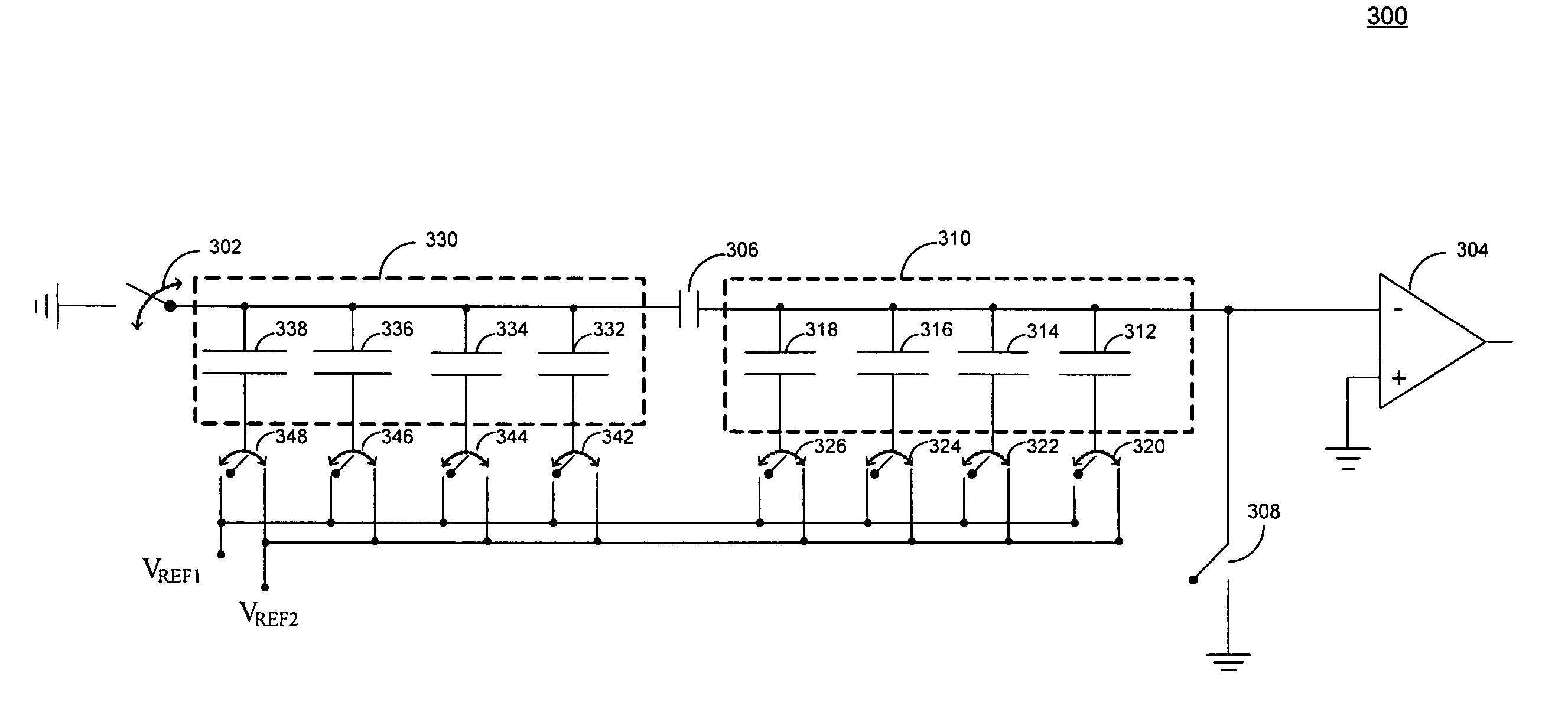
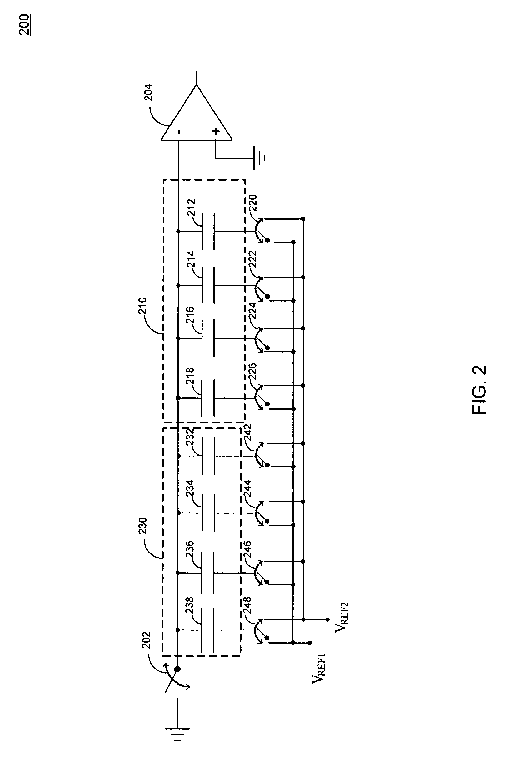
The patent text describes circuits and methods for determining the ratios of components in a system. One method involves using comparison capacitors to quantize analog signals into the digital domain. The lower group of capacitors can also be used to measure residual signals and determine the mismatches of the upper group, eliminating the need for a separate digital-to-analog converter. Another embodiment involves using a subset of elements with known ratios to determine the ratio of an element that affects the system. The invention also includes an electronic circuit that generates a signal proportional to the ratio of components in a circuit, and an analog to digital conversion circuit that operates in both a conversion mode and a calibration mode.

Problems solved by technology

The need for complicated signal processing may also necessitate analog-to-digital conversion because such signal processing is only feasible in the digital domain using either digital computers or special purpose digital signal processors.
Nevertheless, when capacitor values vary due to imprecision associated with manufacturing tolerances, the voltage divider ratios are adversely affected, introducing errors in the preset fractions of the reference level.
This, in turn, introduces errors in the digital quantization process.
This type of architecture, however, suffers from several drawbacks.
For example, the dedicated DAC circuit of these prior art systems are exposed to processing gradients, package stress and other factors which may differ significantly from those of the primary measurement DAC, which may introduce correction factor errors.
The constant capacitive switching associated with this in-the-loop calibration approach introduces noise in the system, adversely affecting the analog portions of the circuit, and undesirably imposes a significant switching load on the reference source, both of which may degrade circuit performance.

Method used


Image

  • Systems and methods for characterizing component ratios and generating a digital representation of same
  • Systems and methods for characterizing component ratios and generating a digital representation of same
  • Systems and methods for characterizing component ratios and generating a digital representation of same

Examples


Embodiment Construction

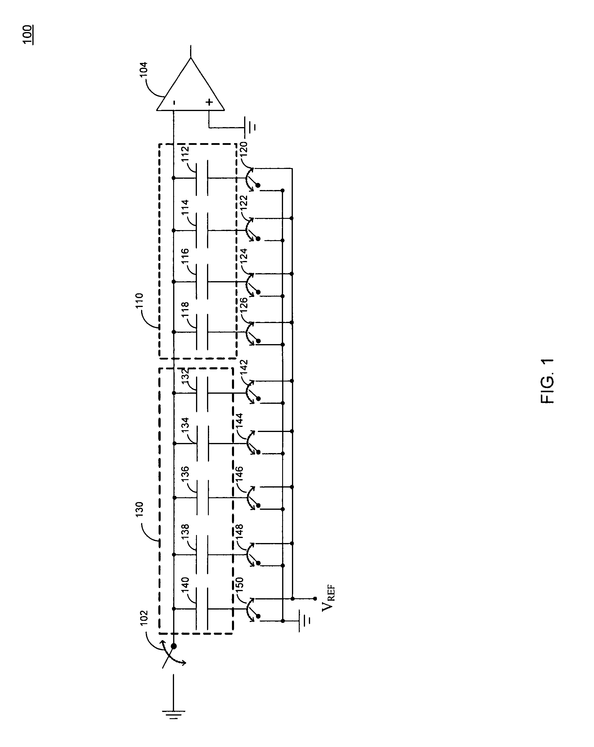
[0026]FIG. 1 shows a schematic diagram of one exemplary embodiment of a circuit 100 for generating a signal that characterizes component ratios in accordance with one aspect of the present invention. Although the following specific embodiments herein relate to the generation of a signal representing component ratios, and in particular capacitive ratios among a group of certain parallel connected capacitors, it will be understood that these specific embodiments are offered to illustrate the present invention, and not serve as limitations. The novel principles expressed herein may be applied to other circuit arrangements, such as determining ratios of other components in any suitable resistive or reactive network, if desired.

[0027]As illustrated, circuit 100 generally includes switch 102, comparator circuit 104, comparison capacitors 112, 114, 116, 118, 132, 134, 136, 138 and 140, and switches 120, 122, 124, 126, 142, 144, 146, 148, 150. The comparison capacitors may be separated into...


PUM


Abstract

Circuits and methods for determining component ratios are provided. An analog to digital converter circuit may include comparison capacitors arranged in an upper group and a lower group for quantizing analog signals into the digital domain. In addition to determining the lower bits during an analog to digital conversion of an input sample, the lower group of comparison capacitors may also be used during calibration mode to quantize a ratio signal that represents the capacitor mismatches of the upper group rather than using a dedicated digital-to-analog converter to perform this function.

Description

BACKGROUND OF THE INVENTION[0001]The invention relates to component ratio determination. More particularly, the invention relates to systems and methods for determining component ratios and the application of correction factors in sampling systems.[0002]Although real world signals are analog, it is often desirable to convert them into the digital domain using analog to digital converters (ADCs). Circuit designers are motivated to perform this conversion because of the efficient methods currently available for the transmission, storage and manipulation of digital signals. A digital representation of an audio signal, for example, allows a CD player to achieve virtually error free storage using optical discs. The need for complicated signal processing may also necessitate analog-to-digital conversion because such signal processing is only feasible in the digital domain using either digital computers or special purpose digital signal processors. Signal processing in the digital domain i...

Claims


Application Information

Patent Timeline
Patent Type & Authority Patents(United States)
IPC IPC(8): H03M1/12
CPCH03M1/1061H03M1/468
Inventor YANG, HEEMIN
Owner ANALOG DEVICES INT UNLTD
Learn More