3-D image observation apparatus

a technology of image observation and 3d, applied in the direction of instruments, optical elements, surgery, etc., can solve the problems of difficult adjustment of the magnification, co-focus of the three optical zoom systems for multiple viewers, and the prior art devices require too much adjustment, so as to improve the patient's safety, facilitate use, and facilitate the effect of viewing postur

Inactive Publication Date: 2010-05-04
OLYMPUS CORP
View PDF10 Cites 9 Cited by
  • Summary
  • Abstract
  • Description
  • Claims
  • Application Information

AI Technical Summary

Benefits of technology

[0017](1) the operator and assistant are given more freedom in selecting viewing postures, and there is less adjustment required by the viewer as a result selecting a different viewing posture;
[0020]Thus, the microscope viewing system of the present invention is easier to use while providing more freedom of viewing postures than prior art devices. Further, the microscope viewing system of the present invention is safer for the patient than microscope viewing systems that do not use electronic display units.

Problems solved by technology

However, prior art surgical microscopes using electronic displays retain the following obstacles to increased usage.
Further, the assistant operator is provided with very limited viewing postures, namely, either directly opposite the operator facing the operator or at the operator's side facing a direction that makes a right angle to the forward direction of the operator.
2) When the operator and assistant share a common optical system, the prior art devices require too much adjustment.
However, it is very difficult to adjust the optical axis, magnification, and co-focus of the three optical zoom systems for multiple viewers.
However, this results in an increase in size of the surgical microscope, more difficulty in adjustment, and greater cost as compared to the present invention.
Further, both wide-angle images and proper eye relief may not be realized at the same time in prior alt devices.
However, no consideration is given to the limited viewing postures available to the operator and assistant or of giving these viewers more freedom of viewing posture.
However, a wide-angle 3-D image is not obtained and the viewing positions are limited to the opposed positions illustrated.
Because a user has little freedom in choice of viewing postures, the viewing experience may be tiresome.
However this would cause the two display panels to physically interfere with each other.
Enlarging these optical zoom systems would likely lead to adjustment problems and oversized systems.
However, in this prior art device, the operator and assistant can only view from positions such that the directions of view are at a right angle to each other; thus, the viewing postures are again limited.
Furthermore, an optical zoom system must be provided for each image detecting device, which makes adjustment troublesome and the size of the microscope larger.
Furthermore, this device requires the operators to wear polarized glasses, which is inconvenient.
However, this prior art device can not realize both a wide-angle field of view and have a large eye relief.
Further, this publication does not disclose, when using multiplexing / demultiplexing of the images, how two operators (e.g., an operator and the assistant) can view an object while sharing a common optical objective, or how they may change their viewing postures and have the images that are presented automatically be adjusted in orientation for the new viewing posture.

Method used


Image

  • 3-D image observation apparatus
  • 3-D image observation apparatus
  • 3-D image observation apparatus

Examples


embodiment 1

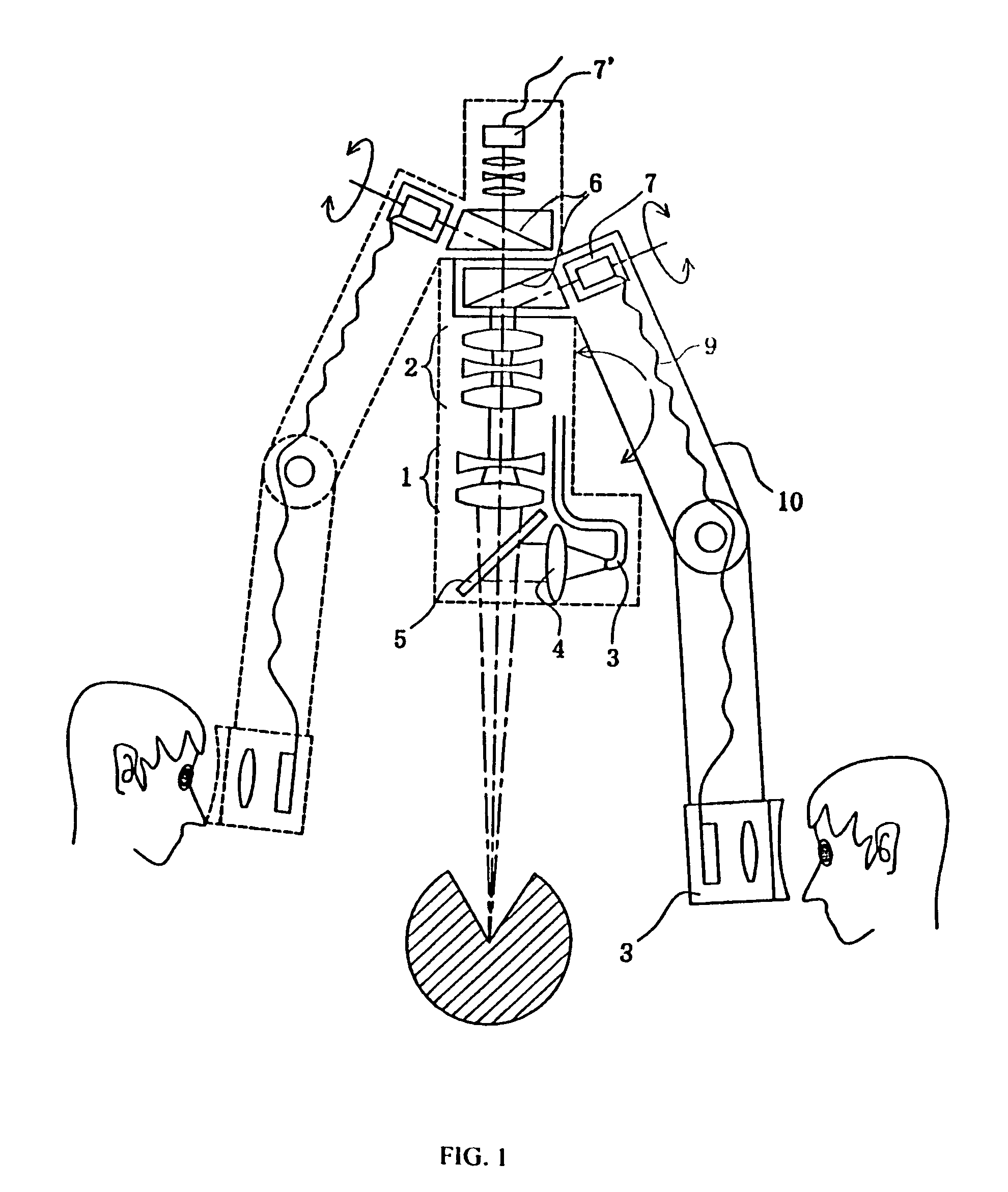
[0065]FIG. 1 is a side, sectional view of the entire surgical microscope of Embodiment 1 of the 3-D viewing system according to the present invention. An optical viewing system and an optical illumination system are provided in the microscope body. The optical viewing system comprises variable objective lenses 1 and an optical zoom system 2. In the optical illumination system, light from a light source (not shown) passes through a light guide 3 and illuminates the surface of an object via a half mirror 5 after being adjusted to a desired convergence angle via an illumination lens 4. Two beam splitters 6, 6 are provided, one for each viewer (operator and assistant) on the optical axis of the optical zoom system 2 within the optical viewing system. At least one of the beam splitters 6,6 (the lower one in this figure) is integrally fixed within an arm 10. Arm 10 is mounted so as to be rotatable around the optical axis of the zoom system 2, which substantially corresponds with the axis ...

embodiment 2

[0070]FIG. 3 is a schematic diagram that illustrates only those portions of Embodiment 2 that differ from Embodiment 1. In this embodiment, rather than a common optical zoom system being provided in the microscope body, individual zoom systems are provided in each optical path following a left or right aperture. Consequently, a total of four optical zoom systems are provided for the operator and assistant. Just as in Embodiment 1, the beam splitter 6 can be rotated around the optical axis according to the viewer position. The imaging section in which the left and right optical zoom systems 2 are mounted can also be rotated around the center axis of the left and right apertures. In this way, just as was shown for Embodiment 1, a main operator and an assistant can view images as if seen from their own position without changing the microscope body, even if they move their position or change their viewing posture. As before, the operators can change their viewpoint to the object without...

embodiment 3

[0071]FIG. 4 is a side, sectional view of a main portion of the surgical microscope of Embodiment 3 of the 3-D viewing system according to the present invention. This embodiment is a modified version of Embodiment 2 shown in FIG. 3. Once more, only the structure that is different from that discussed previously is illustrated. This embodiment comprises, in order from a viewed object: a half mirror 5, variable objective lenses 1, a beam splitter 6, image detecting units 14 (each with an optical coupling means 12 for coupling the optical paths from the left and right apertures in a time-division manner), an optical zoom system 2, an optical imaging system 13, an image detecting device 7 (integrally mounted), and two display panels for the left and right eyes (not shown). As in FIG. 1, a common objective system 1 and an image detecting device 7′ are provided. As before, the beam splitter 6 for the right viewer is integrally fixed to the arm together with the display panels (not shown) o...


PUM


Abstract

A 3-D image observation apparatus includes a reflection type image display panel that has a digital micro mirror device, a magnifying optical system, and at least two light sources. The light sources are positioned at different locations relative to the reflection type image display panel, with the micro mirrors of the digital micro mirror device being variable in tilt angle such that light from a first light source is reflected to the left eye of an observer when the left image is displayed on the display panel in a time-division manner, and light from a second light source is reflected to the right eye of the observer when the right image is displayed on the display panel in a time-division manner. In this manner, one does not need to wear special glasses in order to experience a wide-angle, 3-D viewing experience.

Description

CROSS REFERENCE TO RELATED APPLICATION[0001]This is a divisional application of U.S. application Ser. No. 10 / 359,396 filed Feb. 7, 2003 now abandoned , which application was a continuation of U.S. application Ser. No. 09 / 686,976 filed Oct. 12, 2000, that issued as U.S. Pat. No. 6,525,878 on Feb. 25, 2003. Also, this application claims the benefit of foreign priority of Japanese Patent Application No. H11-293675 filed Oct. 15, 1999, the contents of which are hereby incorporated by reference.BACKGROUND OF THE INVENTION[0002]Three-dimensional (3-D) viewing units and electronic image display units according to the prior art have been described in Japanese Laid Open Patent Applications H5-107482 and H9-511343. As described in Japanese Laid Open Patent Application H5-107482, surgical microscopes that image light fluxes, convert the images into electrical signals, and then display the images are advantageous in that a weaker light can be used to illuminate ophthalmic operations. The weaker...

Claims


Application Information

Patent Timeline
Patent Type & Authority Patents(United States)
IPC IPC(8): G02B27/22G03B21/00A61B19/00G02B21/00G02B21/18G02B21/22G02B21/36G02B27/00G02B27/01G03B35/16
CPCG02B21/0012H04N13/0443G02B21/22G02B21/361G02B27/0093G02B27/017G02B27/0172G02B27/0176G02B27/2228G02B27/2264H04N13/0217H04N13/0402H04N13/0418H04N13/0422H04N13/0427G02B21/18G02B2027/0132G02B2027/0138G02B2027/014G02B2027/0187H04N13/302H04N13/32H04N13/324H04N13/346H04N13/218H04N13/365G02B30/34G02B30/24
Inventor TAKAHASHI, SUSUMU
Owner OLYMPUS CORP
Why Eureka
Try Eureka