Water hammer

a water hammer and hammer head technology, which is applied in the direction of drilling machines, metal working equipment, percussion drilling, etc., can solve the problems of difficult smooth excavating of soil, large amount of water consumed, and bulky addition of equipment for driving the same, so as to reduce the consumption of water and increase the striking force of the hammer. , the effect of increasing the striking force of the bi

Active Publication Date: 2010-05-11
IN
View PDF7 Cites 2 Cited by
  • Summary
  • Abstract
  • Description
  • Claims
  • Application Information

AI Technical Summary

Benefits of technology

[0009]It is another objective of the present invention to provide a drive rod of a boring machine, which can reduce consumption of a large amount of water used to drive the same by operating a piston using a difference in the pressure applied to an internal surface selectively defined by a valve and can be applied to existing boring equipment without special improvement, and a water hammer connected thereto.
[0011]It is yet another objective of the present invention to provide a drive rod of a boring machine, which can increase a striking force of a bit by adding a compressive force to a pneumatic force of a piston for lowering the piston using a water pressure.
[0012]It is a further objective of the present invention to provide a drive rod of a boring machine, which can prevent a piston from malfunctioning due to intermingling of water and air by isolating the air from the water as a pneumatic actuator of a hammer, and can increase a striking force of the hammer using a simplified structure.
[0014]According to another aspect of the present invention, there is provided a water hammer comprising: a tubular main body having a hollow portion; a socket coupled to an upper end of the main body and having a water pressure supply passage; a cylindrical piston housing connected to the main body; a piston slidably installed in the piston housing, having a hollow portion through which water is discharged, an annular pressurizing portion protruding on its outer circumferential surface, and a first communication hole connected to the hollow portion; a sliding member fitted into the main body to be coupled to the piston housing, defining a valve installation space, and creating a space portion in which the piston is received when the piston is elevated; a valve member slidably installed in the valve installation space and defining the same into a first space portion and a second space portion, the cross-sectional area of the first space portion along the length of the piston being larger than that of the second space portion along the length of the first space portion, and the valve member defining a third space portion between the first and second space portions, connected to the hollow portion of the piston; and a water pressure supply unit for supplying pressure water to the first and second space portions to firstly elevate the valve member using a difference between the cross-sectional area of the first space portion and the cross-sectional area of the second space portion to secondly elevate the piston, causing the water used to elevate the housing to be discharged to the hollow portion of the piston in such a manner that the first and second space portions are connected to each other when the piston elevates, and supplying water pressure to the third space portion to cause the valve member to be lowered.

Problems solved by technology

However, for a hard-boring operation, it is necessary to demolish rocks under the ground by dropping a large-sized hammer, requiring additional equipment such as a pile driver.
Thus, as the depth of a bored hole increases, the configuration becomes complicated, and additional equipments for driving the same become bulky.
Particularly, since the bit digs soil using air pressure, it is quite difficult to smoothly excavate the soil as the hole becomes deeper.
In addition, when air is used as a pneumatic actuator of a piston breaker, a large amount of air is consumed, resulting in a considerable increase in the operation cost.
If the pressure of the back head gas chamber is not high enough, the striking force of the bit is undesirably reduced.

Method used


Image

  • Water hammer
  • Water hammer
  • Water hammer

Examples


Embodiment Construction

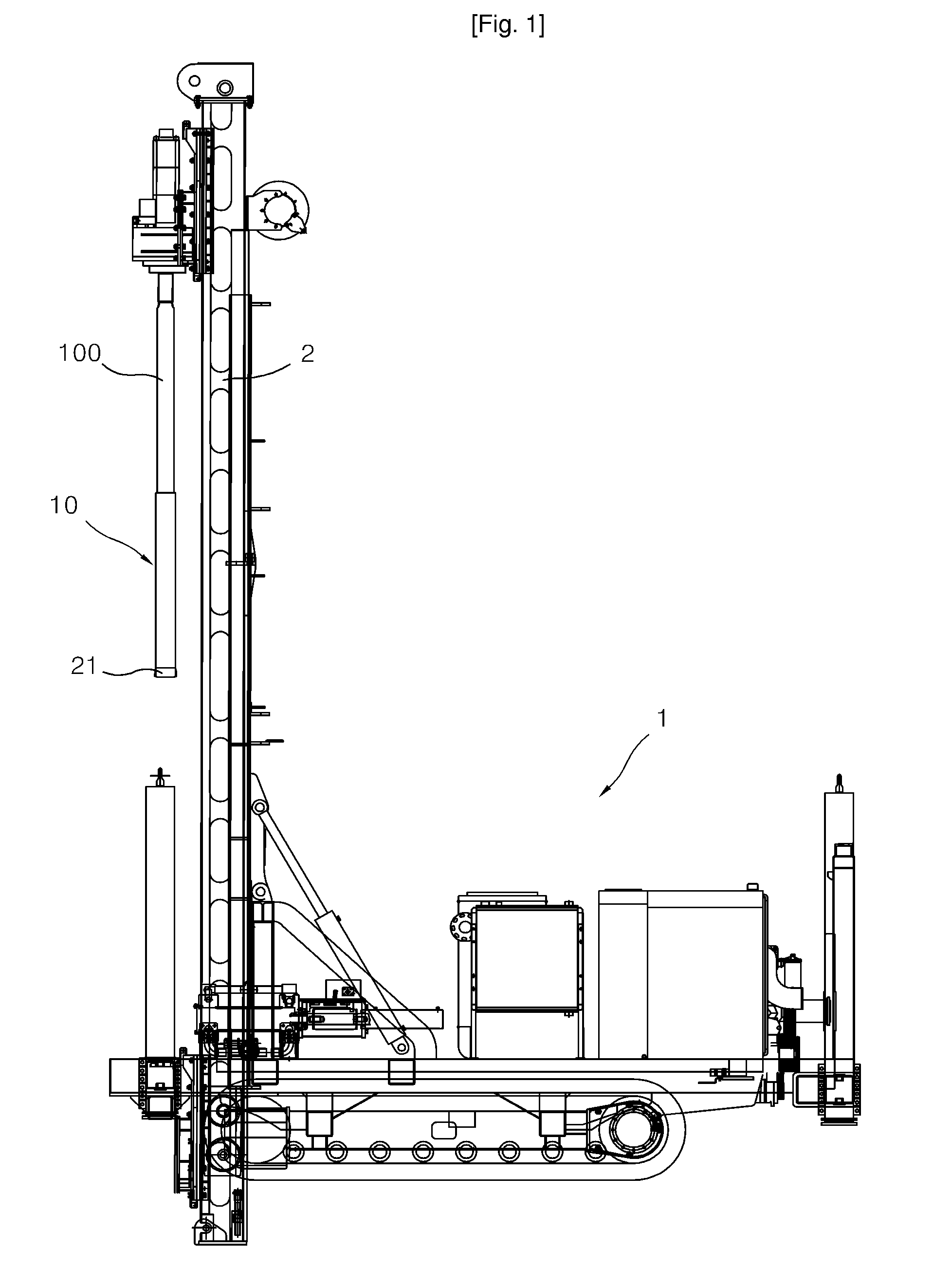
[0025]As shown in FIG. 1, a water hammer 10 according to the present invention is configured to strike a bit 21 guided by the lead 2 and installed at an end portion of a drive rod 100 allowed to be lowered and rotate by means of a driving means in a state in which a lead 2 stands upright perpendicularly with respect to a machine body 1.

[0026]FIGS. 2 and 3 illustrate the water hammer 10 according to an embodiment of the present invention.

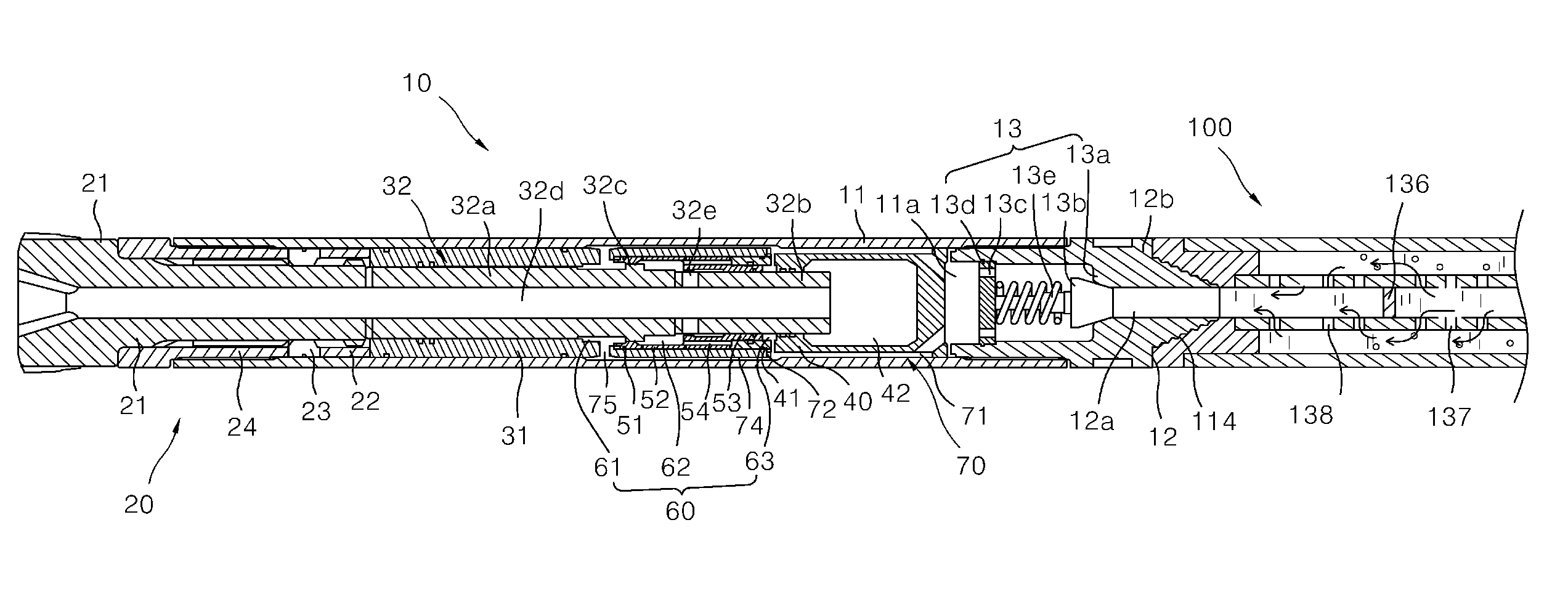
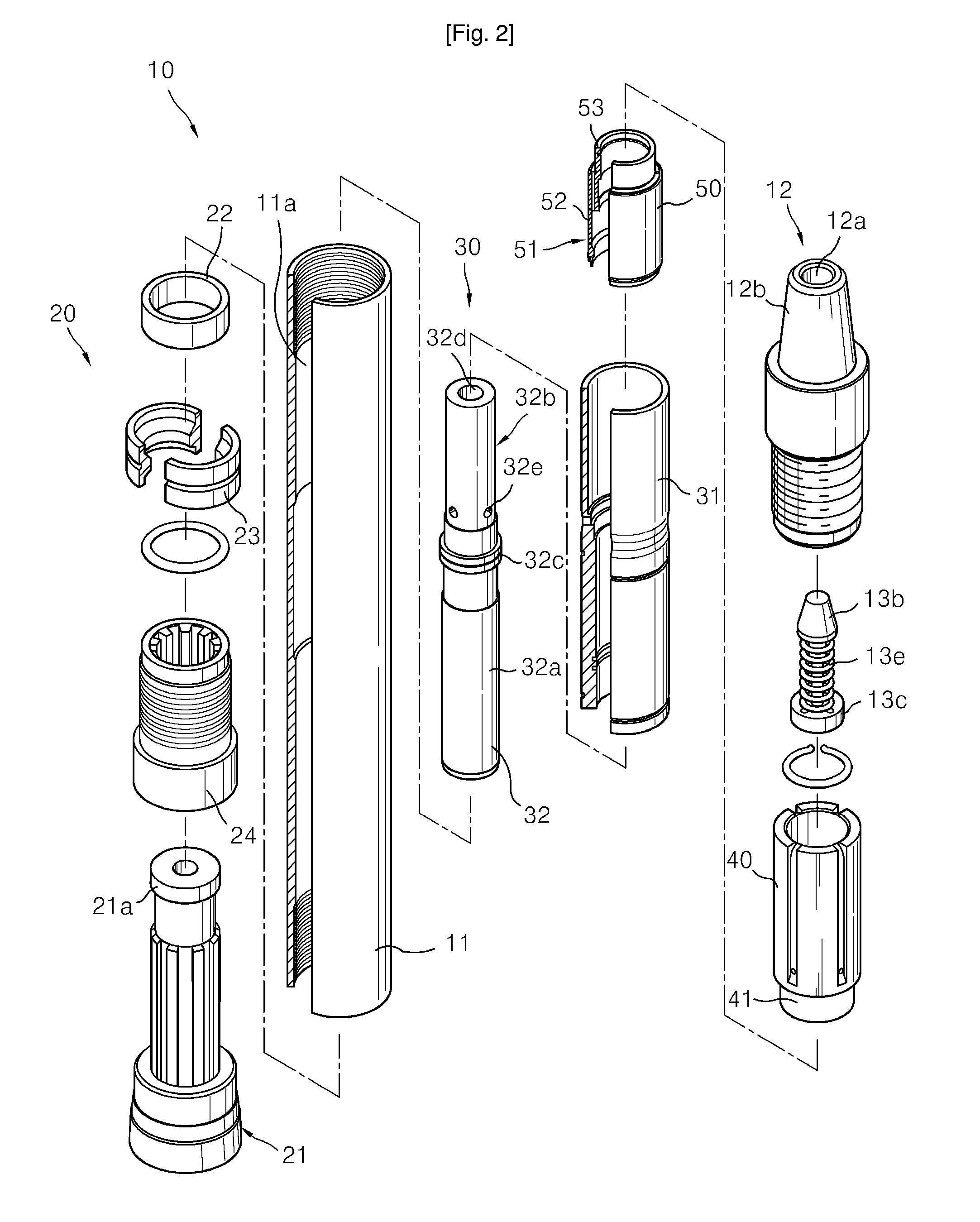
[0027]Referring to the drawings, the water hammer 10 includes a tubular main body 11 having a hollow portion 11a, a socket 12 coupled to an end of the main body 11, having a water pressure supply passage 12a, and connected to the drive rod 100 for supplying high pressure water, a bit unit 20 installed at a lower portion of the main body 11 and having a bit 21 slidably moving lengthwise by a predetermined length to bore holes through rock and soil layers, and a water hammer unit 30 installed in the main body 11 between the socket 12 and the bit unit 2...


PUM


Abstract

A water hammer using a drive rod is provided. The water hammer includes a tubular main body having a hollow portion; a socket coupled to an upper end of the main body and having a water pressure supply passage; a cylindrical piston housing connected to the main body; a piston slidably installed in the piston housing, for striking a bit of a bit unit installed at a lower portion of the main body, having a hollow portion through which water is discharged, an annular pressurizing portion protruding on its outer circumferential surface, and a first communication hole connected to the hollow portion; a sliding member fitted into the main body to be coupled to the piston housing, defining a valve installation space, and creating a space portion in which the piston is received when the piston is elevated; a valve member defining the valve installation space into first and third space portions along the length of the piston, the first and second space portions having different cross-sectional areas from each other, and valve member forming a second space portion between the first and third space portions, connected to the hollow portion of the piston and connected to the first space portion when the piston is elevated; and a water pressure supply unit for supplying high pressure water delivered to the water pressure supply passage of the socket to the first and second space portions.

Description

TECHNICAL FIELD[0001]The present invention relates to a boring machine, and more particularly, to a drive rod of machine which is directly driven using high pressure water and enables a relatively deep hole to be bored in the ground, like a drilling work, and a water hammer using the same.BACKGROUND ART[0002]A boring machine for perforating the ground is generally based on a technique of simply circulating a bit (Oscillating method), a technique of not only circulating a bit or a ball cutter but also pressurizing the same (Reverse Circulation Drilling method: ROC), and so on. According to the oscillating method, in a state in which a standard casing having a diameter of 800 to 3000 mm is clamped by a hydraulic chuck, boring is performed by oscillating a cylinder installed rotatably in a left-right direction. According to the ROC method, the ground is bored using a drive rod having a rotary bit or ball cutter installed at its end portion by rotating the bit or ball cutter. The oscill...

Claims


Application Information

Patent Timeline
Patent Type & Authority Patents(United States)
IPC IPC(8): E21B4/14E21B1/26
CPCE21B4/14
Inventor IN
Owner IN
Why Eureka
Try Eureka