Electrostatic trap

a technology of electrostatic traps and electrostatic peaks, which is applied in the direction of mass spectrometers, particle separator tube details, separation processes, etc., can solve the problems of split peak, poor mass accuracy, and poor quantitation

Active Publication Date: 2010-05-11
THERMO FINNIGAN
View PDF3 Cites 45 Cited by
  • Summary
  • Abstract
  • Description
  • Claims
  • Application Information

AI Technical Summary

Benefits of technology

[0011]According to a second aspect of the present invention, there is provided an electrostatic ion trap for a mass spectrometer comprising an electrode arrangement defining an ion trapping volume, the electrode arrangement being arranged to generate a trapping field defined by a potential U(r,φ,z) where U(r,φ,z) is a potential which traps ions in the Z-direction of the trapping volume so that they undergo substantially isochronous oscillations, wherein the trap further comprises field perturbation means to introduce a perturbation W to the potential U(r,φ,z) so as to enforce a relative shift in the phases of the ions over time such that at least some of the trapped ions have an absolute phase spread of more than zero but less than about 2π radians over an ion detection period Tm.
[0019]Various features of the trap have been ascertained through experiment to result in a perturbation that causes phase bunching to dominate, with the peak from non-bunched ion packets being lost because of a rapid growth in phase shift. Preferred features of the present invention propose controlled distortions to the trap geometry, configuration and / or applied voltages so as to constrain the rate of growth of non-bunched ion packets so that the phase shift does not exceed about 2π radians over the time scale of ion measurement.

Problems solved by technology

In the case of phase bunching, this results in various undesirable artifacts such as the so-called “isotope effect” (explained below), poor mass accuracy, split peaks, poor quantitation (i.e. a distortion of the relation between measured and real intensities of peaks) any one of which may be fatal to the analytical performance of the trap.
Once the phase spread exceeds π radians, ions start to move with opposite phases, resulting in compensating image currents that progressively reduce the overall signal.

Method used


Image

  • Electrostatic trap
  • Electrostatic trap
  • Electrostatic trap

Examples


Embodiment Construction

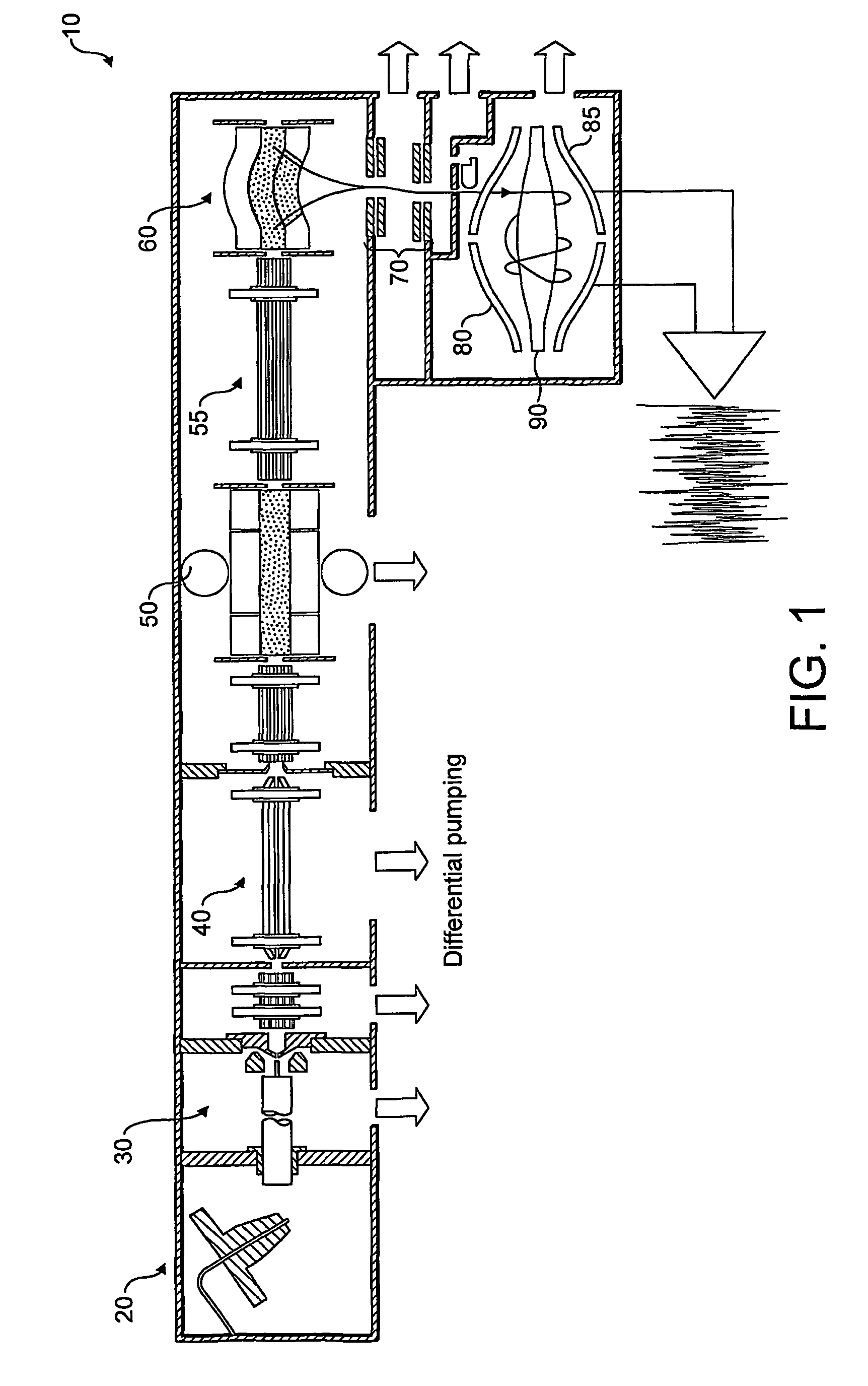
[0036]Referring first to FIG. 1, a schematic arrangement of a mass spectrometer including an electrostatic trap and an external storage device is shown. The arrangement of FIG. 1 is described in detail in commonly assigned WO-A-02 / 078046 and will not be described in detail here. A brief description of FIG. 1 is, however, included in order better to understand the use and purpose of the electrostatic trap to which the present invention relates.

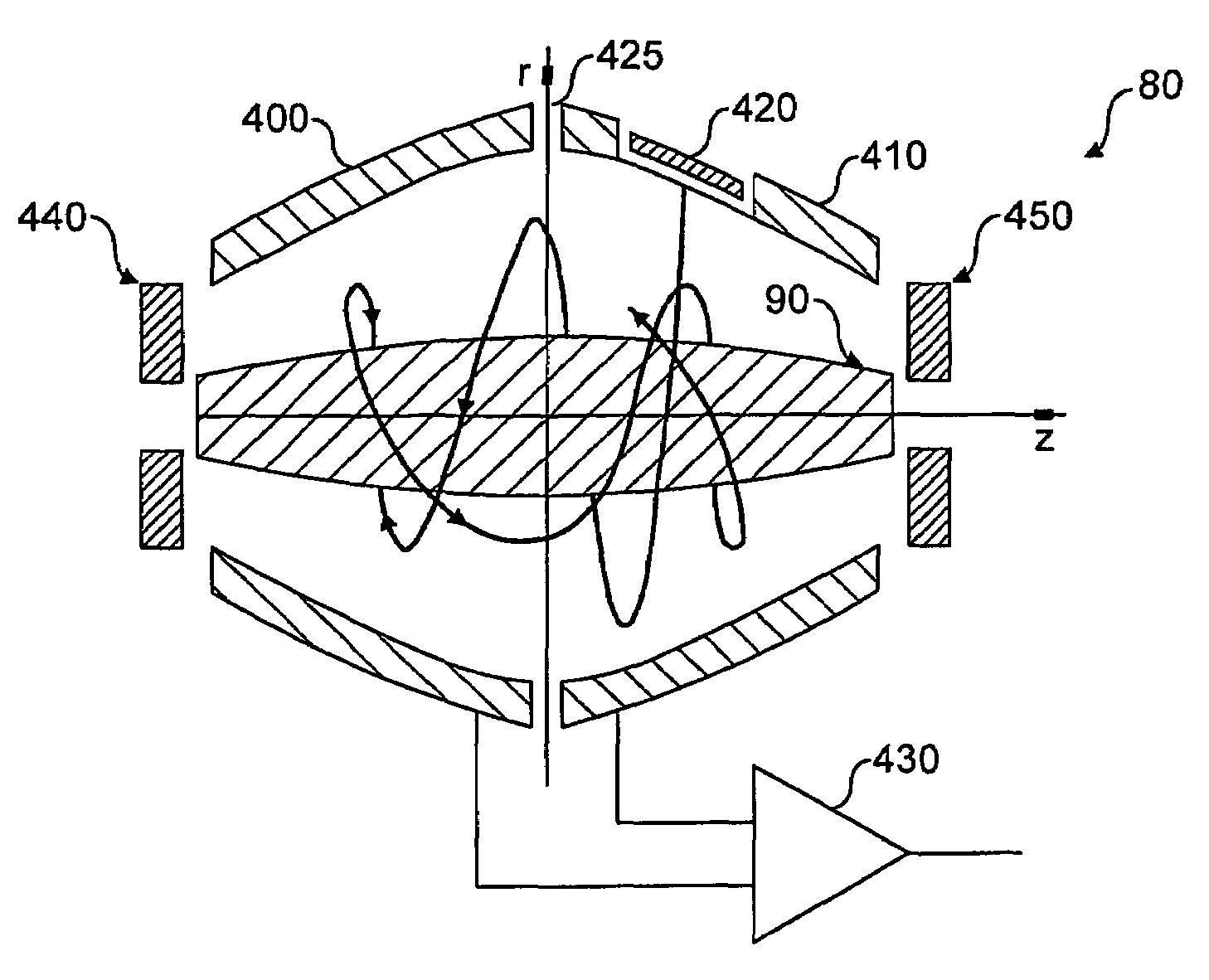
[0037]As seen in FIG. 1, the mass spectrometer 10 includes a continuous or pulsed ion source 20 which generates gas-phase ions. These pass through an ion source block 30 into an RF transmission device 40 which cools ions. The cooled ions then enter a linear ion trap acting as a mass filter 50 which extracts only those ions within a window of mass charge ratios of interest. Ions within the mass range of interest then proceed via a transfer octapole device 55 into a curved trap 60 which stores ions in a trapping volume through application of an R...


PUM


Abstract

An electrostatic trap such as an orbitrap is disclosed, with an electrode structure. An electrostatic trapping field of the form U′(r,φ,z) is generated to trap ions within the trap so that they undergo isochronous oscillations. The trapping field U′(r, φ,z) is the result of a perturbation W to an ideal field U(r, φ,z) which, for example, is hyperlogarithmic in the case of an orbitrap. The perturbation W may be introduced in various ways, such as by distorting the geometry of the trap so that it no longer follows an equipotential of the ideal field U(r, φ,z), or by adding a distortion field (either electric or magnetic). The magnitude of the perturbation is such that at least some of the trapped ions have an absolute phase spread of more than zero but less than about 2π radians over an ion detection period Tm.

Description

FIELD OF THE INVENTION[0001]This invention relates to improvements in an electrostatic trap (EST), that is, a mass analyser of the type where ions injected into it undergo multiple reflections within a field that is substantially electrostatic during ion detection, i.e., any time dependent fields are relatively small. It relates in particular but not exclusively to improvements in the Orbitrap mass analyser first described in U.S. Pat. No. 5,886,346.BACKGROUND OF THE INVENTION[0002]Electrostatic traps (ESTs) are a class of ion optical devices where moving ions experience multiple reflections in substantially electrostatic fields. Unlike in RF fields, trapping in electrostatic traps is possible only for moving ions. To ensure this movement takes place and also to maintain conservation of energy, a high vacuum is required so that the loss of ion energy over a data acquisition time Tm is negligible.[0003]There are three main classes of EST: linear, where ions change their direction of ...

Claims


Application Information

Patent Timeline
Patent Type & Authority Patents(United States)
IPC IPC(8): H01J49/28H01J49/42
CPCH01J49/425H01J49/02H01J49/282H01J49/0027H01J49/42H01J49/4245H01J49/406
Inventor MAKAROV, ALEXANDERDENISOV, EDUARD V.JUNG, GERHARDBALSCHUN, WILKOHORNING, STEVAN ROY
Owner THERMO FINNIGAN
Why Eureka
Try Eureka