Illumination system for a microlithography projection exposure installation

Inactive Publication Date: 2010-05-11
CARL ZEISS SMT GMBH
View PDF35 Cites 41 Cited by
  • Summary
  • Abstract
  • Description
  • Claims
  • Application Information

AI Technical Summary

Benefits of technology

[0011]The object of the invention is thus to provide an illumination system for a microlithography projection exp

Problems solved by technology

Appropriate changing devices c

Method used


Image

  • Illumination system for a microlithography projection exposure installation
  • Illumination system for a microlithography projection exposure installation
  • Illumination system for a microlithography projection exposure installation

Examples


Embodiment Construction

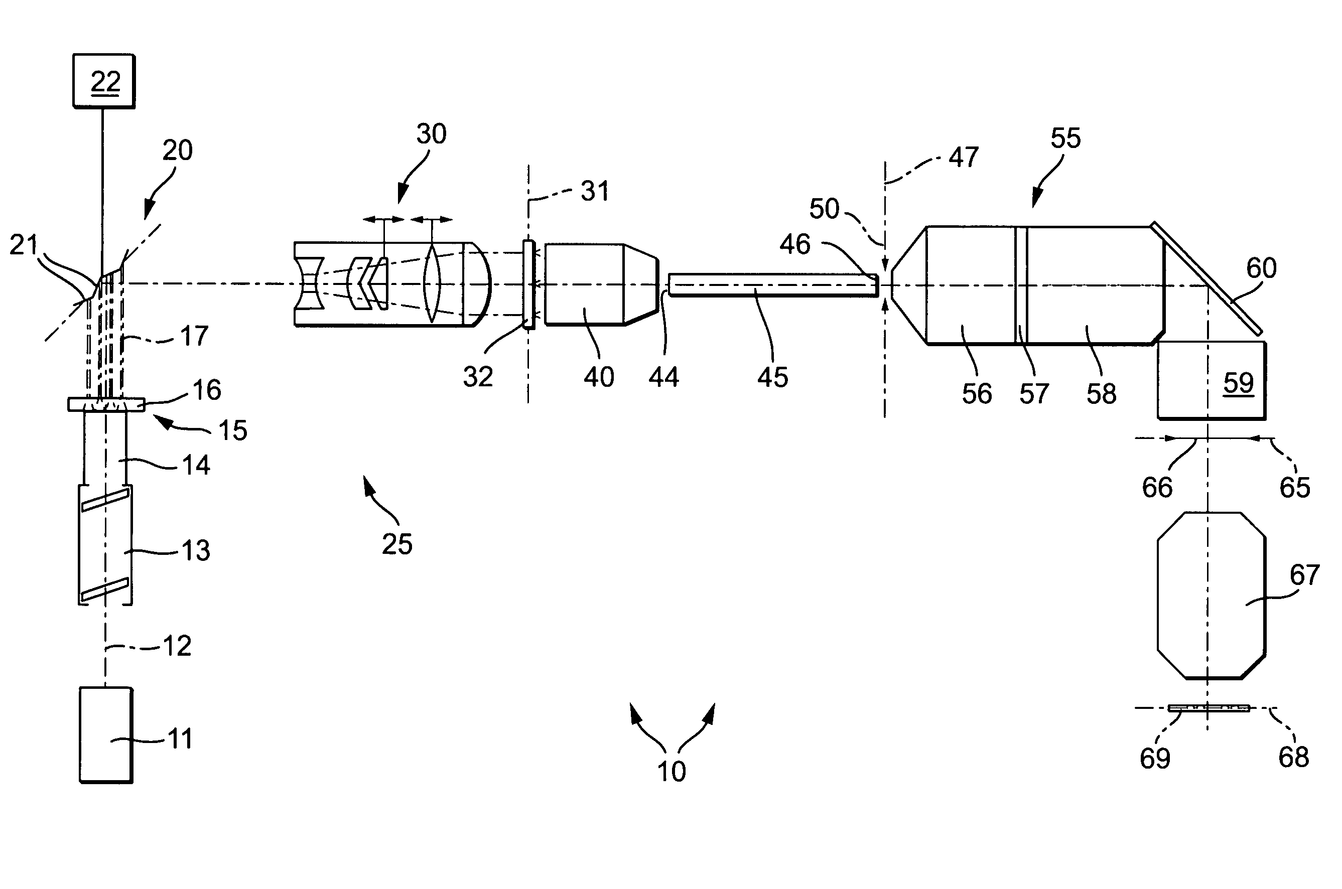
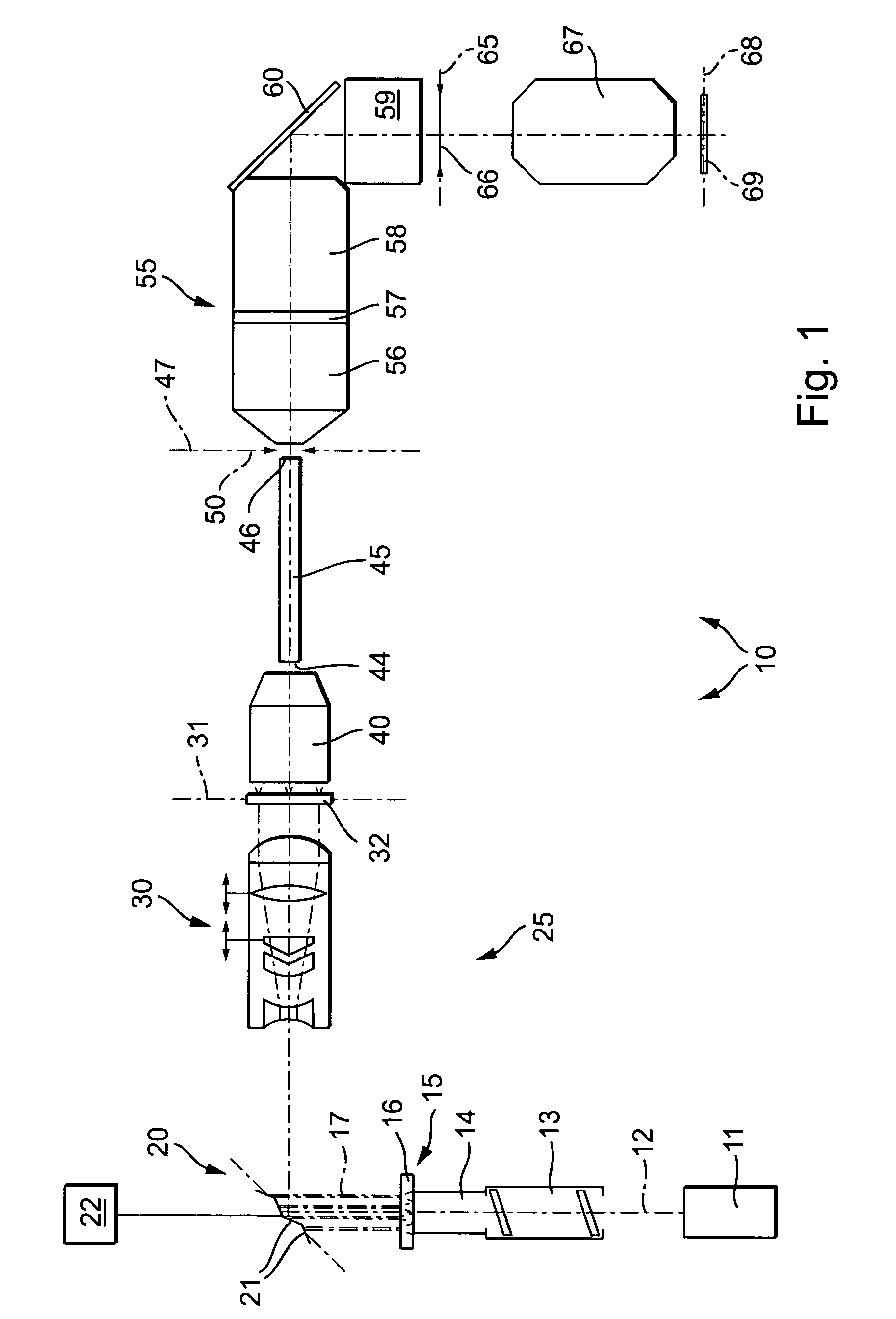
[0047]FIG. 1 shows an example of an illumination system 10 of a projection exposure system for microlithography, which can be used in the production of semiconductor components and other finely structured components and, in order to achieve resolutions down to fractions of micrometers, operates with light from the deep ultraviolet range. The light source 11 used is an F2 excimer laser having an operating wavelength of about 157 nm, whose light beam is aligned coaxially with respect to the optical axis 12 of the illumination system. Other UV light sources, for example ArF excimer lasers with 193 nm operating wavelength, KrF excimer lasers with 248 nm operating wavelength or mercury vapour lamps with 365 nm or 436 nm operating wavelength or light sources with wavelengths below 157 nm are likewise possible.

[0048]The light from the light source 11 is firstly incident into a beam expander 13, which widens the laser beam and, from the original beam profile with a cross section of 20 mm×15...


PUM


Abstract

An illumination system for a microlithography projection exposure installation is used to illuminate an illumination field with the light from a primary light source (11). The illumination system has a light distribution device (25) which receives light from the primary light source and, from this light, produces a two-dimensional intensity distribution which can be set variably in a pupil-shaping surface (31) of the illumination system. The light distribution device has at least one optical modulation device (20) having a two-dimensional array of individual elements (21) that can be controlled individually in order to change the angular distribution of the light incident on the optical modulation device. The device permits the variable setting of extremely different illuminating modes without replacing optical components.

Description

CROSS-REFERENCE TO RELATED APPLICATIONS[0001]This application is a National Stage Entry of International Application No. PCT / EP2004 / 010188, filed on Sep. 13, 2004 in the European Patent Office. This application claims priority from DE 103 43 333.3, filed on Sep. 12, 2003 in the German Patent Office, and DE 10 2004 010 571.5, filed on Feb. 26, 2004 in the German Patent Office. The entire disclosures of the prior applications are hereby incorporated by reference.BACKGROUND OF THE INVENTION[0002]1. Field of the Invention[0003]The invention relates to an illumination system for a microlithography projection exposure system for illuminating an illumination field with the light from a primary light source.[0004]2. Description of the Related Art[0005]The efficiency of projection exposure systems for the microlithographic production of semiconductor components and other finely structured components is determined substantially by the imaging properties of the projection objectives. Furthermo...

Claims


Application Information

Patent Timeline
IPC IPC(8): G03B27/54G03B27/42G03B27/72G03F7/20
CPCG03F7/702G03F7/70116G03F7/20
Inventor KOEHLER, JESSWANGLER, JOHANNESBROTSACK, MARKUSSINGER, WOLFGANGFIOLKA, DAMIANMAUL, MANFRED
Owner CARL ZEISS SMT GMBH
Why Eureka
Try Eureka