
Engine hood assembly enclosure with exhaust aftertreatment device integrated therein, and machine using same

a technology of exhaust aftertreatment and enclosure, which is applied in the direction of machines/engines, mechanical equipment, transportation and packaging, etc., can solve the problems of not requiring substantial and costly redesign of the machine, not taking into account the more current need to treat exhaust for more than noise emissions, and limited space available for the incorporation of exhaust aftertreatment devices

Active Publication Date: 2010-05-18
CATERPILLAR INC
View PDF23 Cites 44 Cited by
  • Summary
  • Abstract
  • Description
  • Claims
  • Application Information

AI Technical Summary

Benefits of technology

The patent describes a machine with an engine-based propulsion system that has an engine hood with an enclosure. The enclosure has ventilation openings and at least one exhaust aftertreatment device is mounted inside. The engine exhaust pipe is connected to the aftertreatment device through an opening in the bottom of the enclosure. An exhaust stack extends through the top of the enclosure and is connected to the aftertreatment device. The technical effects of this invention include improved engine performance, reduced emissions, and improved fuel efficiency.

Problems solved by technology

As a consequence, limited spatial envelopes are available for the incorporation of exhaust aftertreatment devices, without requiring substantial and costly redesign of the machine.
While this strategy better integrates noise suppression mufflers into the overall machine design, it fails to account for a more current need to treat exhaust for more than noise emissions.
In particular, the current D10 tractor has limited space available for incorporation of exhaust aftertreatment devices while maintaining heat rejection standards for the engine and maintaining other requirements, such as operator visibility.

Method used


Image

  • Engine hood assembly enclosure with exhaust aftertreatment device integrated therein, and machine using same
  • Engine hood assembly enclosure with exhaust aftertreatment device integrated therein, and machine using same
  • Engine hood assembly enclosure with exhaust aftertreatment device integrated therein, and machine using same

Examples


Embodiment Construction

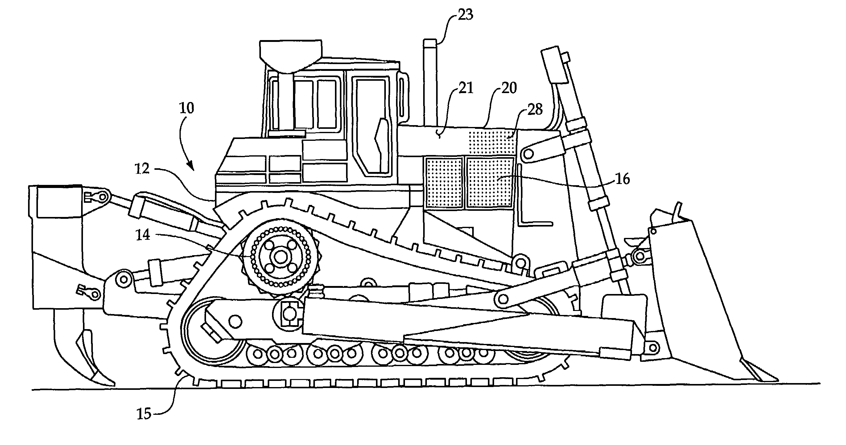
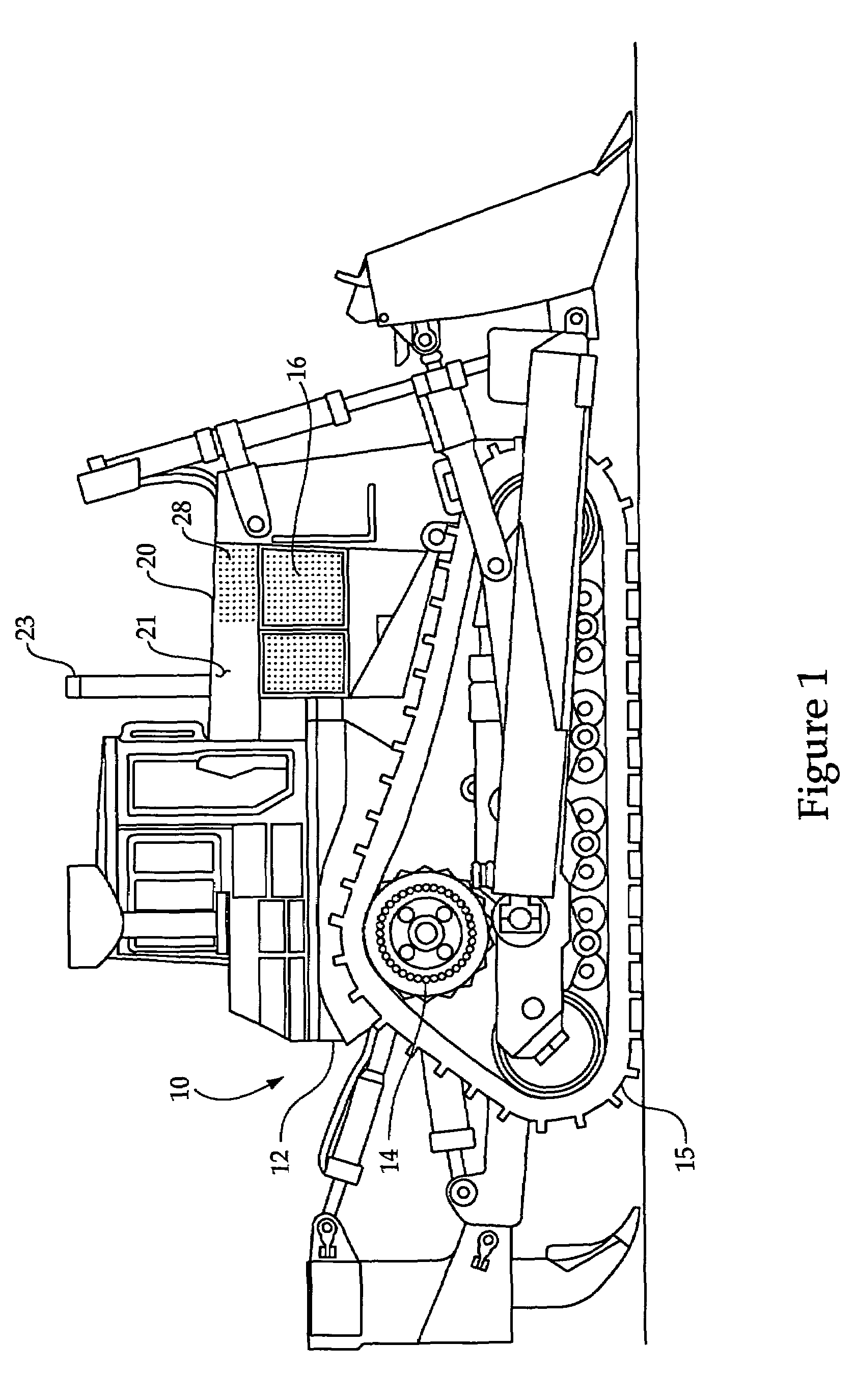
[0012]Referring to FIG. 1, a machine 10 includes a frame 12 upon which a propulsion system 14 is mounted. In this specific example, machine 10 is a relatively large track-type tractor, and the propulsion system 14 includes a diesel engine 16 that provides power to propel machine 10 via track 15 in a conventional manner. The engine 16 is positioned in an engine compartment that is covered by an engine hood assembly 20. Exhaust from engine 16 is vented to atmosphere via an exhaust stack 23 that protrudes through the top surface of hood assembly 20. Hood assembly 20 includes an enclosure 21 that defines a plurality of ventilation openings 28, which may be distributed in a rectangular array of rows and columns.

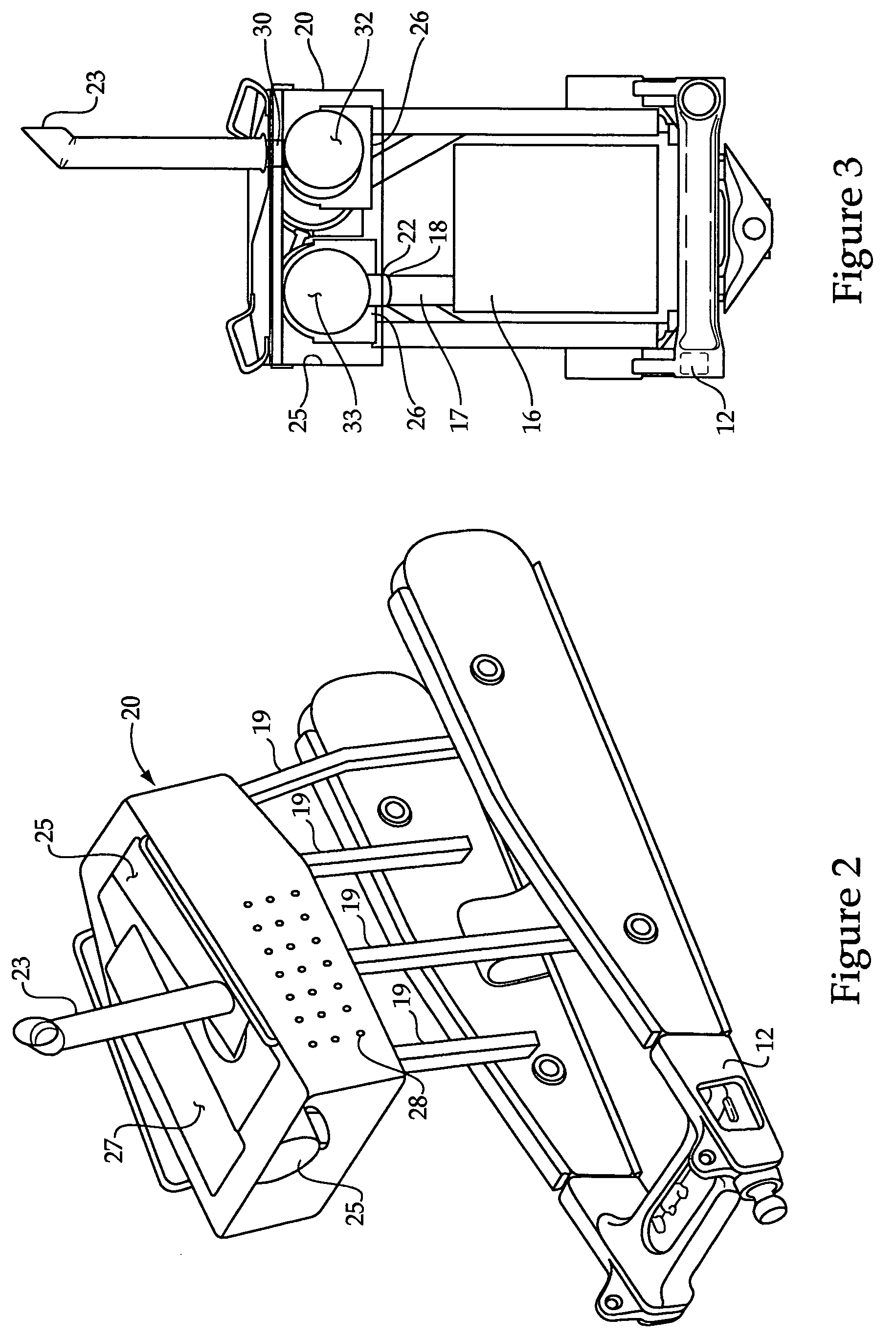
[0013]Referring now in addition to FIGS. 2-4, various features associated with hood assembly 20 are illustrated. As stated earlier, hood assembly 20 includes an enclosure 21 that may be manufactured in any suitable manner such as via sheet metal and / or steel plates joined in any s...


PUM


Abstract

A hood assembly for a machine includes an enclosure within which at least one exhaust aftertreatment device is mounted. The engine hood assembly may be preassembled so that the exhaust aftertreatment system is integrated into the enclosure. This may allow the hood assembly to be assembled to the machine and the exhaust aftertreatment system mated to an exhaust pipe from the engine as a unit while the machine is being built on an assembly line. The engine hood assembly may include ventilation openings to assist in heat rejection from the engine compartment and from the exhaust aftertreatment devices. The hood assembly of the present disclosure finds particular application in assisting large track type tractors in meeting ever more stringent exhaust emission requirements without extensive and expensive redesign alternatives.

Description

TECHNICAL FIELD[0001]The present disclosure relates generally to the incorporation of exhaust aftertreatment devices into machines, and more particularly to an engine hood assembly enclosure that houses at least one exhaust aftertreatment device.BACKGROUND[0002]Regulations governing exhaust emissions from internal combustion engines are becoming increasingly more stringent in many jurisdictions. Among the regulated exhaust emissions are NOx, particulate matter and hydrocarbons. Many machines utilize internal combustion engines as a means of powering propulsion systems, work implements and the like. Among these machines are track-type tractors, wheel loaders, compactors, excavators, graders, forestry machines, scrapers, and many others. While great strides have been made in reducing undesirable engine exhaust emissions at the point of combustion using a variety of innovative techniques, it may still be necessary to treat engine exhaust before venting via a tail pipe to the atmosphere...

Claims


Application Information

Patent Timeline
Patent Type & Authority Patents(United States)
IPC IPC(8): B60K11/00F01N13/08
CPCB60K13/04F01N13/009F01N2250/02F01N2260/022F01N2590/08F01N2250/14
Inventor KERTZ, TONY G.BRIAN, CHRISTOPHER M.
Owner CATERPILLAR INC
Learn More