
High pressure, high voltage penetrator assembly for subsea use

a high-voltage penetrator and assembly technology, applied in the direction of connection contact member materials, instruments, borehole/well accessories, etc., can solve the problems of creep current and voltage breakdown, electric flash-over, explosion, ignition of production gas, etc., and achieve the effect of safe assembly operation

Inactive Publication Date: 2010-05-18
INGENIOR HARALD BENESTAD
View PDF8 Cites 12 Cited by
  • Summary
  • Abstract
  • Description
  • Claims
  • Application Information

AI Technical Summary

Benefits of technology

[0026]a ceramic sleeve surrounding the terminals and an adjacent part of the conductive pin and the cable thereat,

Problems solved by technology

The gas which is used for cooling the motor is both wet, as it may contain water, and polluted, as it normally will contain electrically conductive particles and a large variety of other impurities which may lead to electrical flash-over, creep currents and voltage breakdown.
In a worst scenario, such operating conditions may lead to ignition of the production gas and explosion, with catastrophic consequences.
Further, during a wet gas production, a rapid decompression may occur, and as a result devices such as O-rings and electrical insulation which have been exposed to high pressure, may simply explode, giving rise to the risk of fatal breakdown of the compressor subsea installation.
In view of on one hand to require optimum withdrawal of gas from a production well and therefore the need to increase the pressure therein to expel the gas from the reservoir, and on the other hand the tough and hazardous environment in which a subsea compressor unit has to work, with related implications if an operation failure is about to happen and is not detected in time to take counter-measures to prevent it happen, has been a headache to the profession and a challenge which has existed for years without a satisfactory solution to overcome the well known operational problems.

Method used


Image

  • High pressure, high voltage penetrator assembly for subsea use
  • High pressure, high voltage penetrator assembly for subsea use
  • High pressure, high voltage penetrator assembly for subsea use

Examples


Embodiment Construction

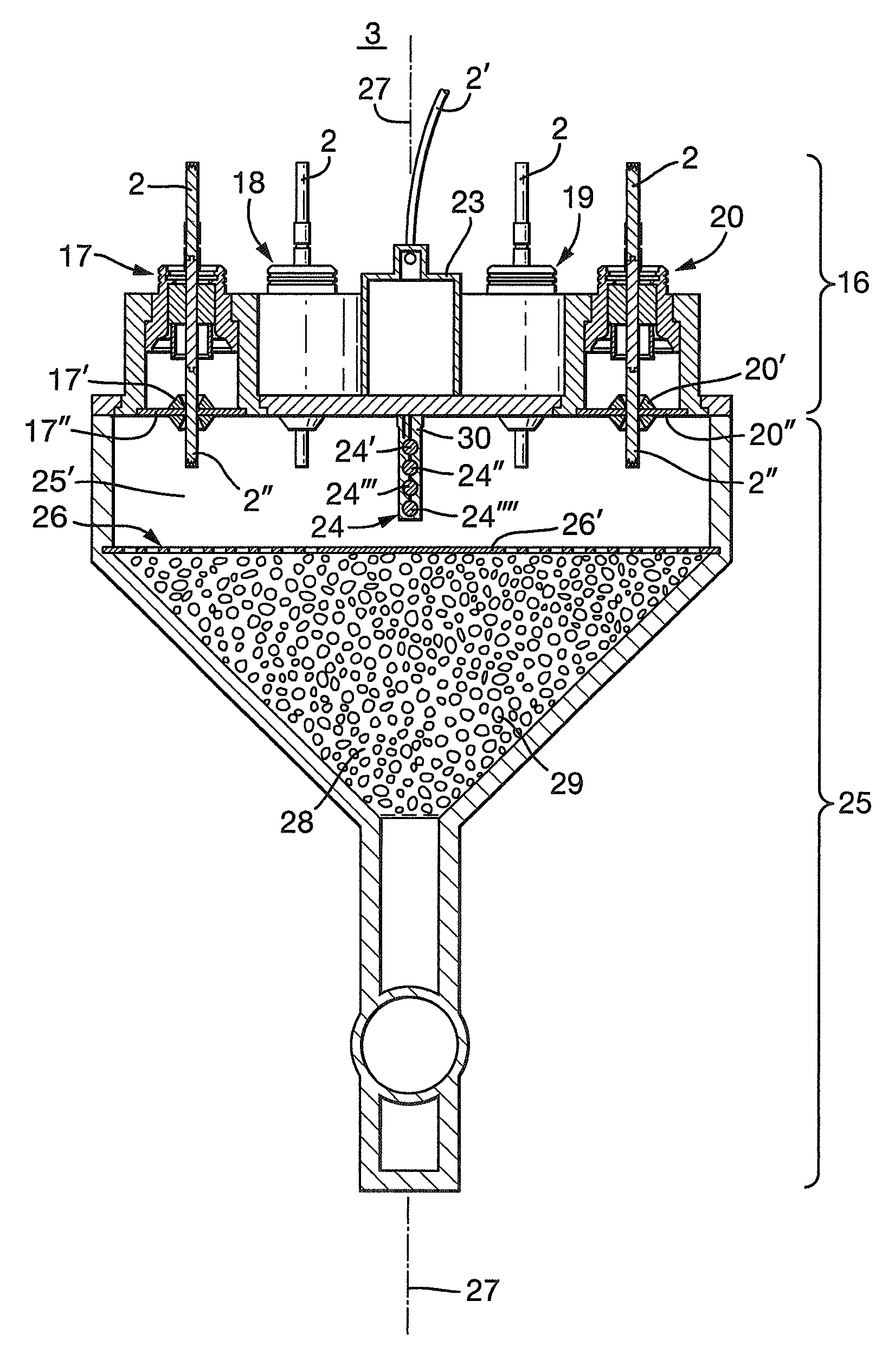
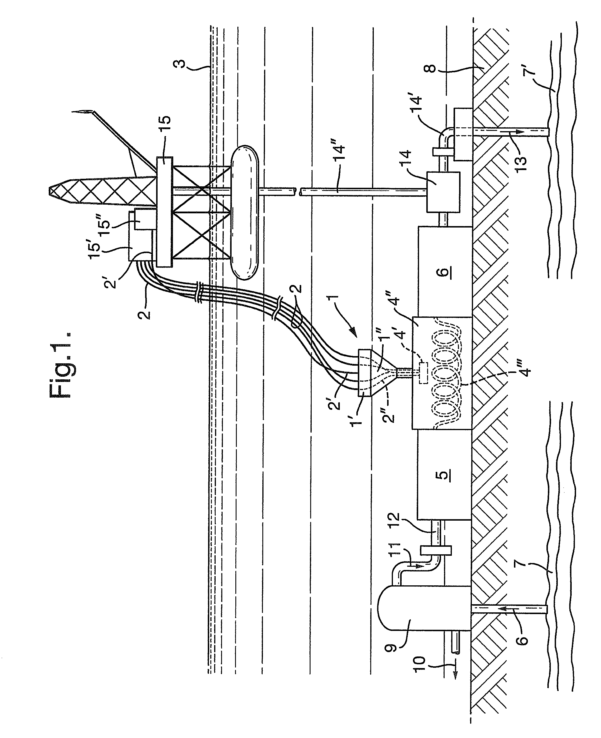
[0040]FIG. 1 shows a typical working environment of the penetrator assembly 1 with power cables 2 and signal cables 2′ extending down from a surface 3′ of a sea 3 and the power cables 2 powered by a generator 15′ on an offshore installation, e.g. an offshore platform 15 (for simplicity not shown to scale relative to a compressor unit 4, 5, 6 on the sea bed 8). The signal cables 2′ lead to a signal processing station 15″ on the installation 15. The power cables 2 are relayed through the penetrator unit 1′ of the assembly 1, and further power cables 2″ extend from the penetrator unit 1′ through the inside 1″ of the assembly down into motor connection terminals 4′ inside a housing 4″ of a motor 4 which is configured to drive an upstream installed wet gas compressor 5 and a downstream wet gas compressor 6.

[0041]The compressor receives gas 6 from a reservoir 7 below the seabed 8, and the gas passes through a separator 9 which delivers a gas condensate 10 and passes gas 11 which is still ...


PUM


Abstract

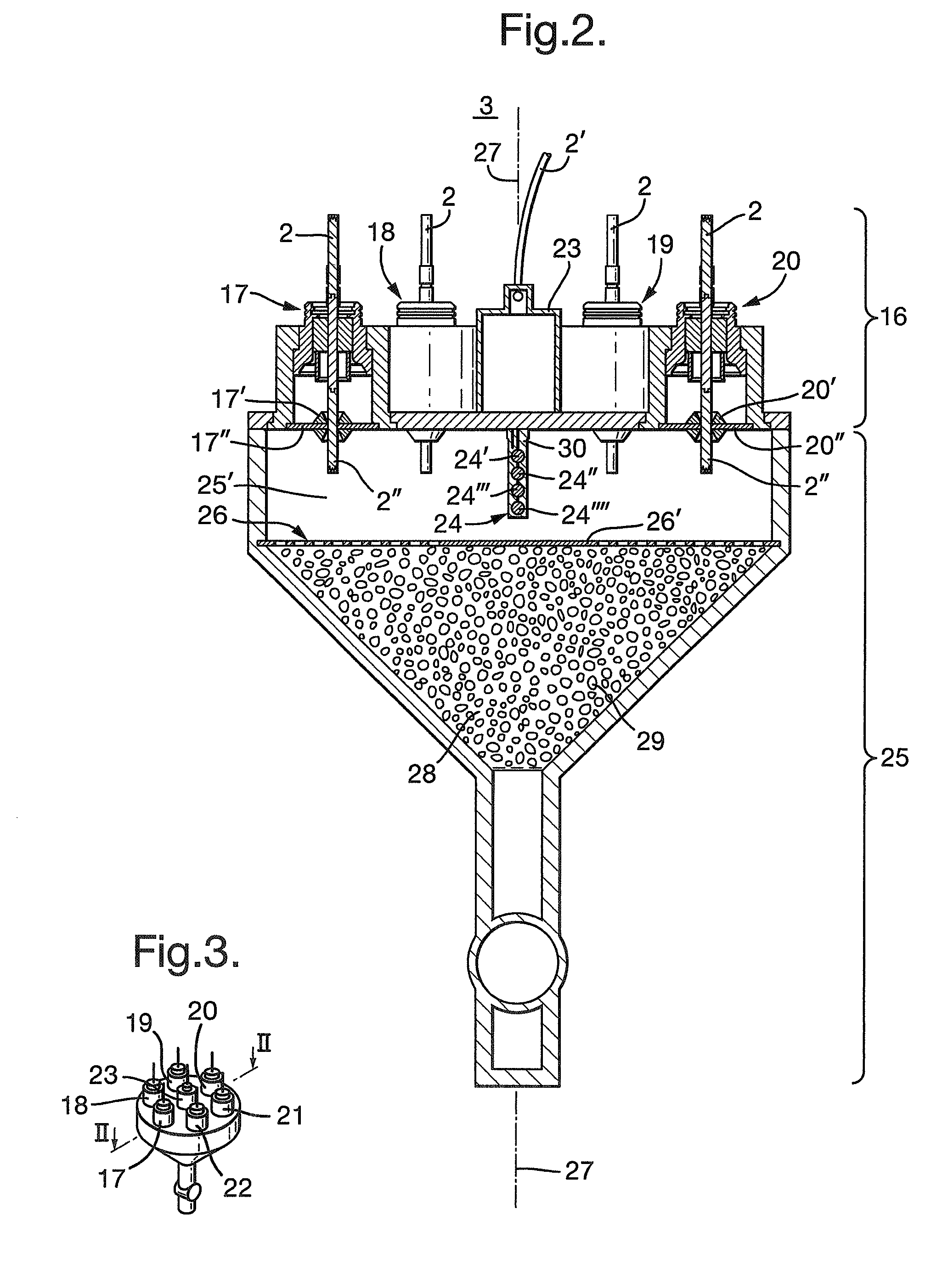
The invention relates to a high pressure, high voltage penetrator assembly for subsea use, wherein the assembly is upright attachable to a wet gas, subsea gas compressor, and wherein the assembly includes a penetrator unit for feed-through of electric power to a compressor motor; a funnel shaped housing with a housing chamber, the penetrator unit being located at an upper end of the chamber; a grid located inside the chamber transversely of a longitudinal axis of the chamber, the penetrator unit being located above the grid, a filter located in the chamber below the grid and above an inlet to a housing of the compressor motor, and a sensor unit extending into the chamber from the penetrator unit and towards, but spaced from the grid.

Description

CROSS REFERENCE TO RELATED APPLICATIONS[0001](Not Applicable)STATEMENT REGARDING FEDERALLY SPONSORED RESEARCH OR DEVELOPMENT[0002](Not Applicable)NAMES OF THE PARTIES TO A JOINT RESEARCH AGREEMENT[0003](Not Applicable)INCORPORATION BY REFERENCE OF MATERIALS SUBMITTED ON A COMPACT DISC[0004](Not Applicable)[0005]The present invention relates to a high pressure, high voltage penetrator assembly for subsea use, as defined in the preamble of attached claim 1. Further, the invention relates to a high voltage penetrator for use in a penetrator unit of the assembly, as defined in the preamble of claim 7.BACKGROUND OF THE INVENTION[0006]In order to stabilize and increase hydrocarbon process gas (wet gas) delivery from a production well, whether subsea or topside, a compressor is usually installed downstream of a coarse liquid separation, The compressor requires a drive motor with a high power rating, usually in a current range of 500-2000 A and a voltage range of 6.6-12 kVAC.[0007]It is imp...

Claims


Application Information

Patent Timeline
IPC IPC(8): H01B17/26
CPCH01B17/30E21B41/0007E21B33/0385H02G9/12H02G15/23H02G15/32
Inventor BENESTAD, HARALDBENESTAD, PAL GEORG
Owner INGENIOR HARALD BENESTAD
Learn More