Ion mobility spectrometer and ion-mobility-spectrometry/mass-spectrometry hybrid spectrometer
a mobility spectrometer and hybrid technology, applied in the direction of instruments, particle separator tube details, separation processes, etc., can solve the problems of high cost, ions which have passed through the acceleration region during between respective acceleration timings, and are los
- Summary
- Abstract
- Description
- Claims
- Application Information
AI Technical Summary
Benefits of technology
Problems solved by technology
Method used
Image
Examples
1st embodiment
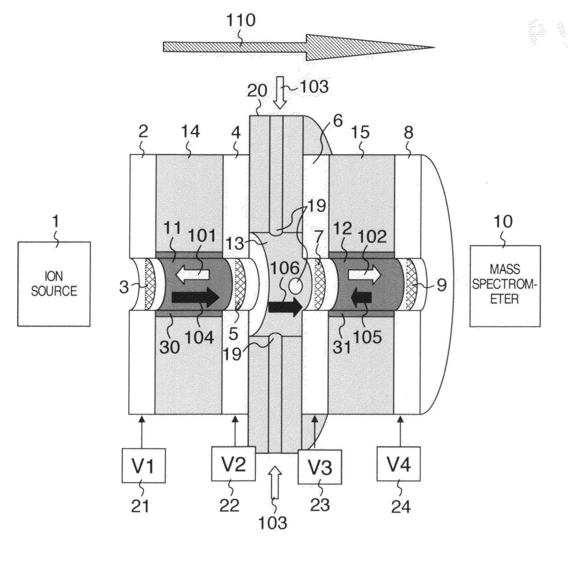
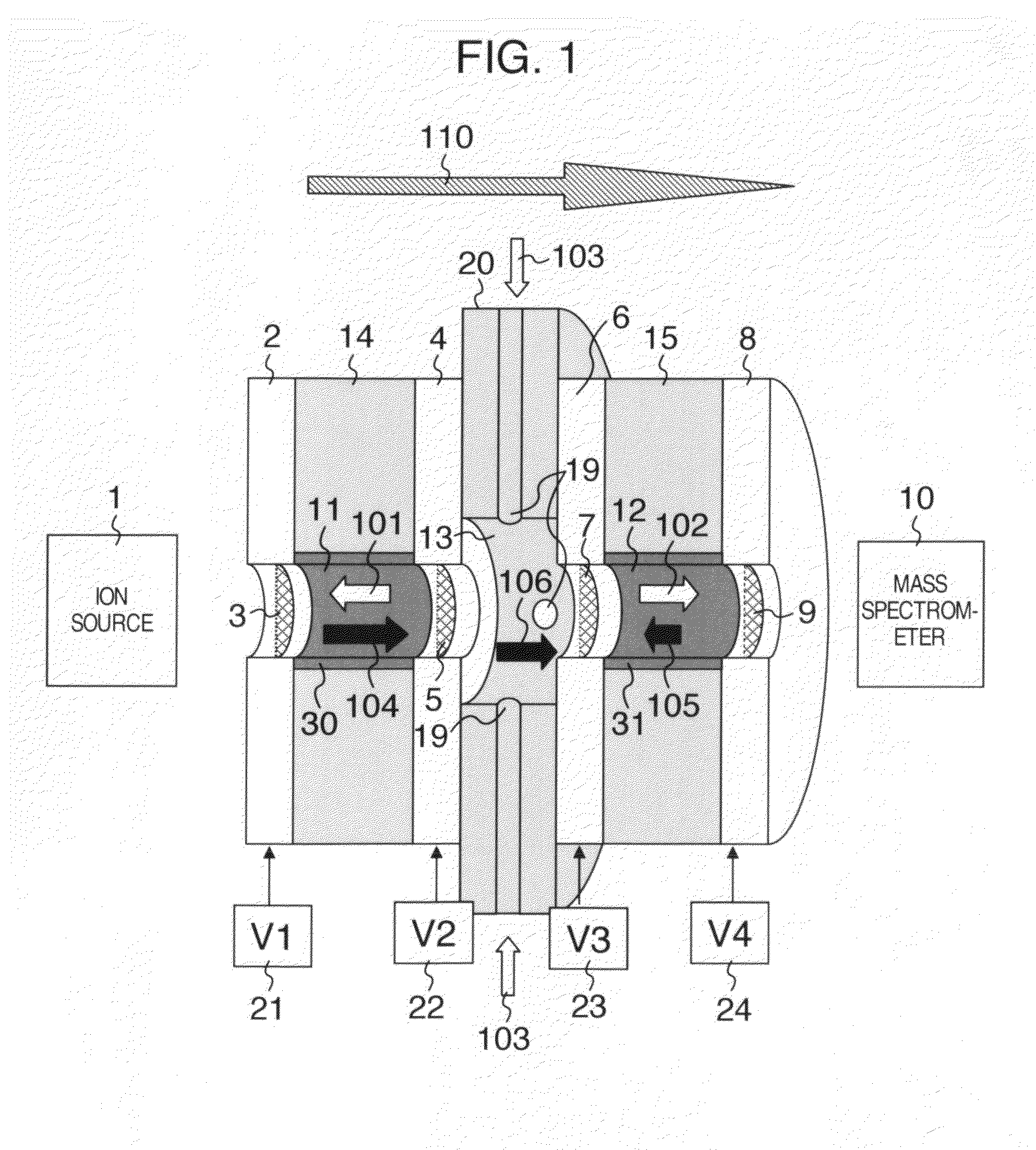
[0027]FIG. 1 is a configuration diagram of an ion mobility spectrometer in which the present scheme is carried out. First, ions are generated by an atmospheric-pressure ion source 1, such as atmospheric-pressure chemical ion source, electrospray ion source, and atmospheric-pressure matrix-assisted laser desorption ion source. Next, the ions generated pass through a small orifice (substantially 0.1 mmφ to 10 mmφ, which is denoted by D) of a first inlet electrode 2, then being introduced into a first drift region 11. The first drift region 11 is surrounded by the first inlet electrode 2 and a first exit electrode 4. Here, the ion source is not limited to the atmospheric-pressure ion source, but whatever ion source is available as long as it can ionize the sample. The first drift region 11 is equal to substantially 1 mm to 100 mm in length.
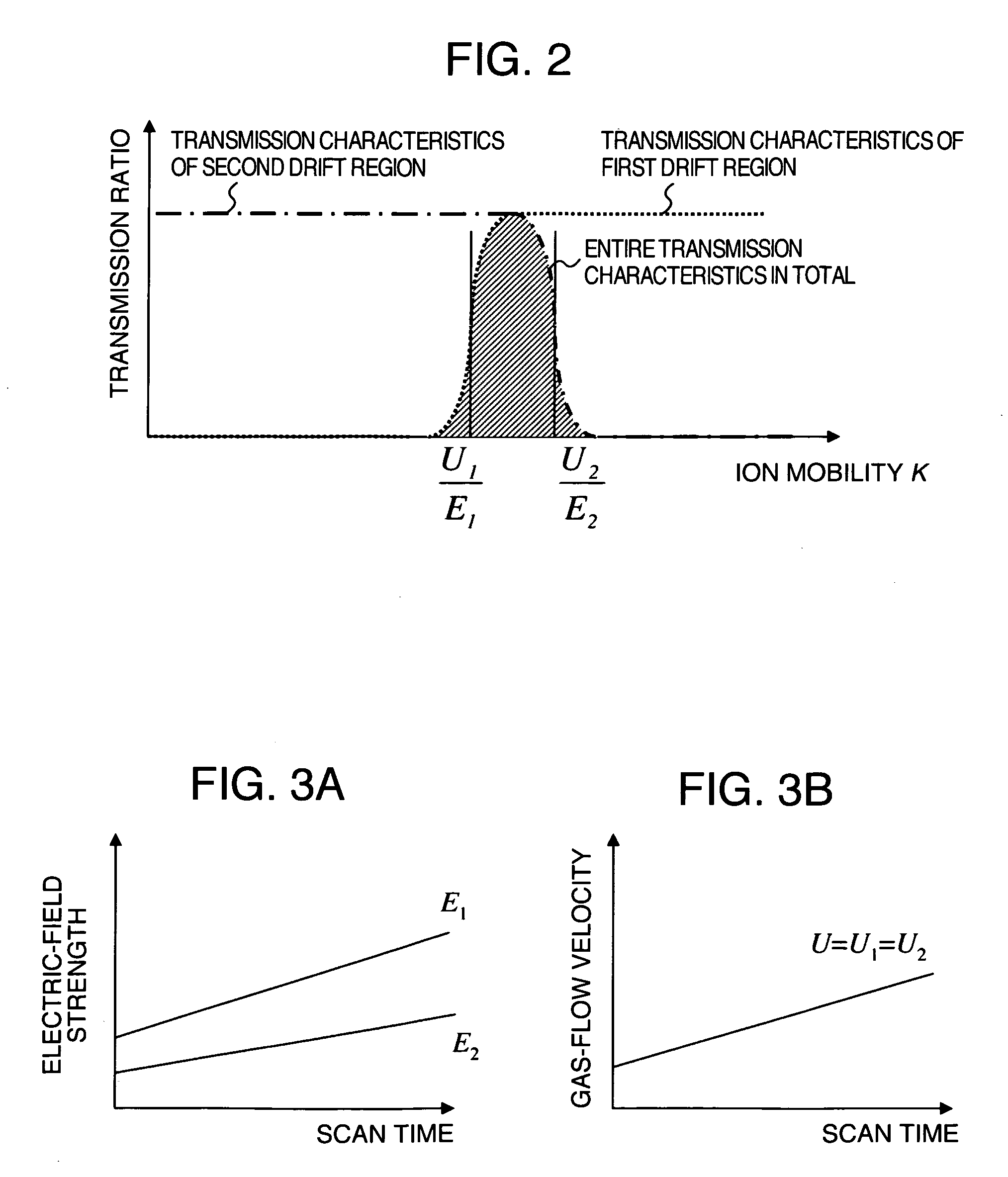
[0028]In the first drift region 11, there occurs a velocity vector 104, which is caused to occur towards the ions in an ion traveling direction 110 ...
2nd embodiment
[0043]FIG. 4 illustrates a second embodiment of the present invention. In the second embodiment, the ions generated from the ion source are sent to the detector or the in-vacuum mass spectrometer 10 via the first drift region 11 and the second drift region 12. This process is basically the same as the one in the first embodiment. In the second embodiment, however, the gas-flow direction in each drift region is opposite to the one in the first embodiment. Concretely, the gas is pumped in the direction indicated by 103, using a (not-illustrated) pump. Also, in accompaniment with the changes in the gas-flow directions, the direction and strength of each electric field differ from the ones in the first embodiment. In the second embodiment, only an ion which satisfies the following (Expression 6) can pass through the first drift region 11, and only an ion which satisfies the following (Expression 7) can pass through the second drift region 12. As a consequence, only an ion which satisfie...
3rd embodiment
[0046]The foregoing embodiments are the embodiments where the two drift regions having the mutually different electric-field directions are arranged in series. FIG. 6 illustrates a third embodiment where the ion mobility spectrometer is combined with the mass spectrometer. In the mass spectrometer, the ions can be separated based on differences in the masses. As a result, as the ion mobility spectrometer which is the preceding-stage spectrometer to the mass spectrometer, only the coarse separation is required in some cases. In the first and second embodiments, the ions having a specific range (its upper-limit value and lower-limit value exist) of ion mobility have been permitted to pass therethrough. In the present embodiment, however, the explanation will be given below concerning an example of the ion-mobility spectrometry filter in the first drift region 11 alone.
[0047]Of the ions generated by the ion source 1, only the ions whose ion mobility is lower than a certain specific val...
PUM
 Abstract
Description
Claims
Application Information
 - R&D
- Intellectual Property
- Life Sciences
- Materials
- Tech Scout
- Unparalleled Data Quality
- Higher Quality Content
- 60% Fewer Hallucinations
Browse by: Latest US Patents, China's latest patents, Technical Efficacy Thesaurus, Application Domain, Technology Topic, Popular Technical Reports.
© 2025 PatSnap. All rights reserved.Legal|Privacy policy|Modern Slavery Act Transparency Statement|Sitemap|About US| Contact US: help@patsnap.com


