Charging system for legged mobile robot

a mobile robot and charging system technology, applied in the direction of remote-control toys, instruments, coupling device connections, etc., can solve the problems of over-charging, power consumption during charging, and displacement of the center of gravity of the robot, so as to facilitate the positioning of the robot and improve the charging system

Inactive Publication Date: 2010-05-18
HONDA MOTOR CO LTD
View PDF3 Cites 114 Cited by
  • Summary
  • Abstract
  • Description
  • Claims
  • Application Information

AI Technical Summary

Benefits of technology

[0009]An object of the present invention is to improve a charging system for a legged mobile robot. More specifically, in order to eliminate the disadvantages described above, an object of the present invention is to provide a charging system that facilitates positioning of a robot to be charged and does not put a load on the robot. Another object of the present invention is to provide a charging system that prevents a power receiving terminal from being soiled or deteriorated and does not make any nearby person from feeling uncomfortable.
[0010]In order to attain the objects described above, a charging system for a legged mobile robot according to the present invention is a charging system that charges a battery of a legged mobile robot, comprising: a charging station on which the robot is charged, in which the robot includes a power receiving connector having a power receiving terminal, and the charging station includes a charging power supply that outputs a charging current to the battery, a power supplying connector designed to be connected to the power receiving connector, a power supplying terminal provided on the power supplying connector and designed to come into contact with the power receiving terminal, guide means that guides the robot to reduce the misalignment between the power receiving connector and the power supplying connector in a predetermined direction when the robot comes close to the charging station for charging, and moving means for moving the guide means in the predetermined direction by the force exerted on the guide means as the robot comes close to the charging station.
[0011]In the charging system according to the present invention, if the robot comes close to the charging station to be charged on the charging station, the guide means guides the robot to reduce the misalignment between the power receiving connector and the power supplying connector in the predetermined direction. When the robot is guided by the guide means, a force that moves the robot and the guide means relative to each other in the predetermined direction occurs between the robot and the guide means. When such a force occurs between the two, the moving means moves the guide means in the predetermined direction. Accordingly, there is no need to adjust the joints of knees, ankles or the like to compensate for the misalignment on the part of the robot, so that the robot can be charged in a natural, reasonable posture, and therefore, the robot can be easily controlled. As a result, unlike conventional systems, no power is consumed for maintaining the unreasonable posture of the robot, and thus, the robot can be quickly charged.

Problems solved by technology

However, in the case of the legged mobile robot, if the hip part is moved horizontally by moving the joints of knees, ankles or the like without displacing the legs, the center of gravity of the robot is displaced, and therefore, the robot has to be charged with the joints being subjected to a moment.
If the robot is charged with the joints being subjected to a moment as described above, additional power is required to maintain the posture of the robot, and there is a possibility that the power consumption during charging increases.
If the power receiving connector is displaced by displacing the legs, the legs of the robot are displaced with the power receiving connector and the power supplying connector being partially in contact with each other, so that the connectors are overloaded, and the connectors can be damaged.
Furthermore, the power receiving terminal disclosed in Japanese Patent Laid-Open No. 2001-179663 is always exposed to the outside, and therefore, if the surface of the terminal is soiled with something, the electrical contact between the power receiving terminal and the power supplying terminal can be poor.
Furthermore, in the case of the arrangement disclosed in Japanese Patent Laid-Open No. 2001-179663, if spark discharge (ark discharge) occurs when the power receiving terminal and the power supplying terminal are connected to each other for charging of the robot or disconnected from each other after charging of the robot, the spark discharge can cause deterioration of the terminals, the deterioration of the terminals can cause an increase of the resistance between the terminals, and the increase of the resistance can cause heat generation.

Method used


Image

  • Charging system for legged mobile robot
  • Charging system for legged mobile robot
  • Charging system for legged mobile robot

Examples


Embodiment Construction

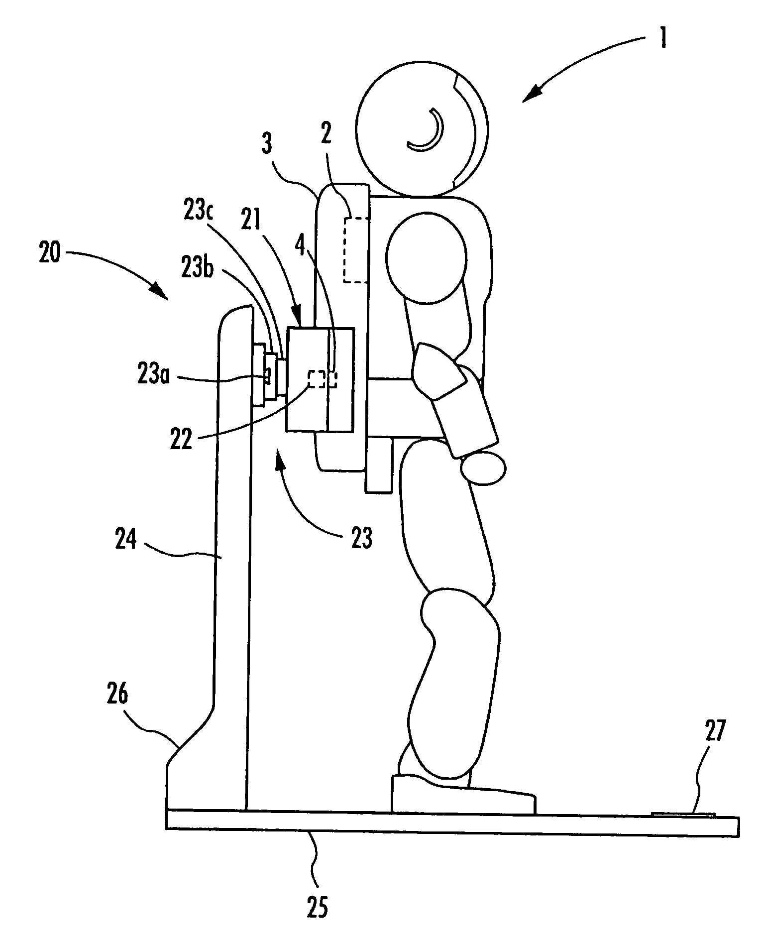
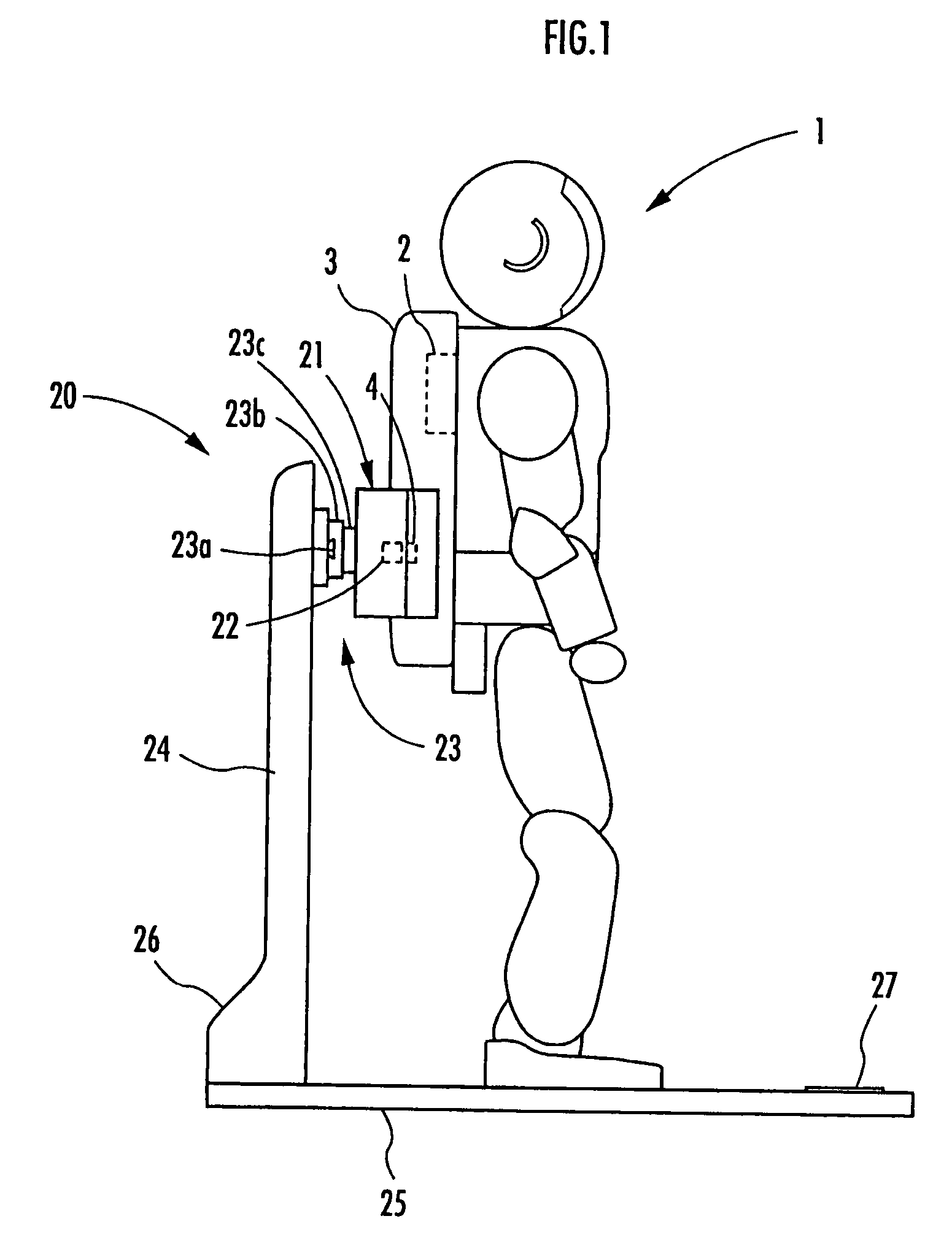
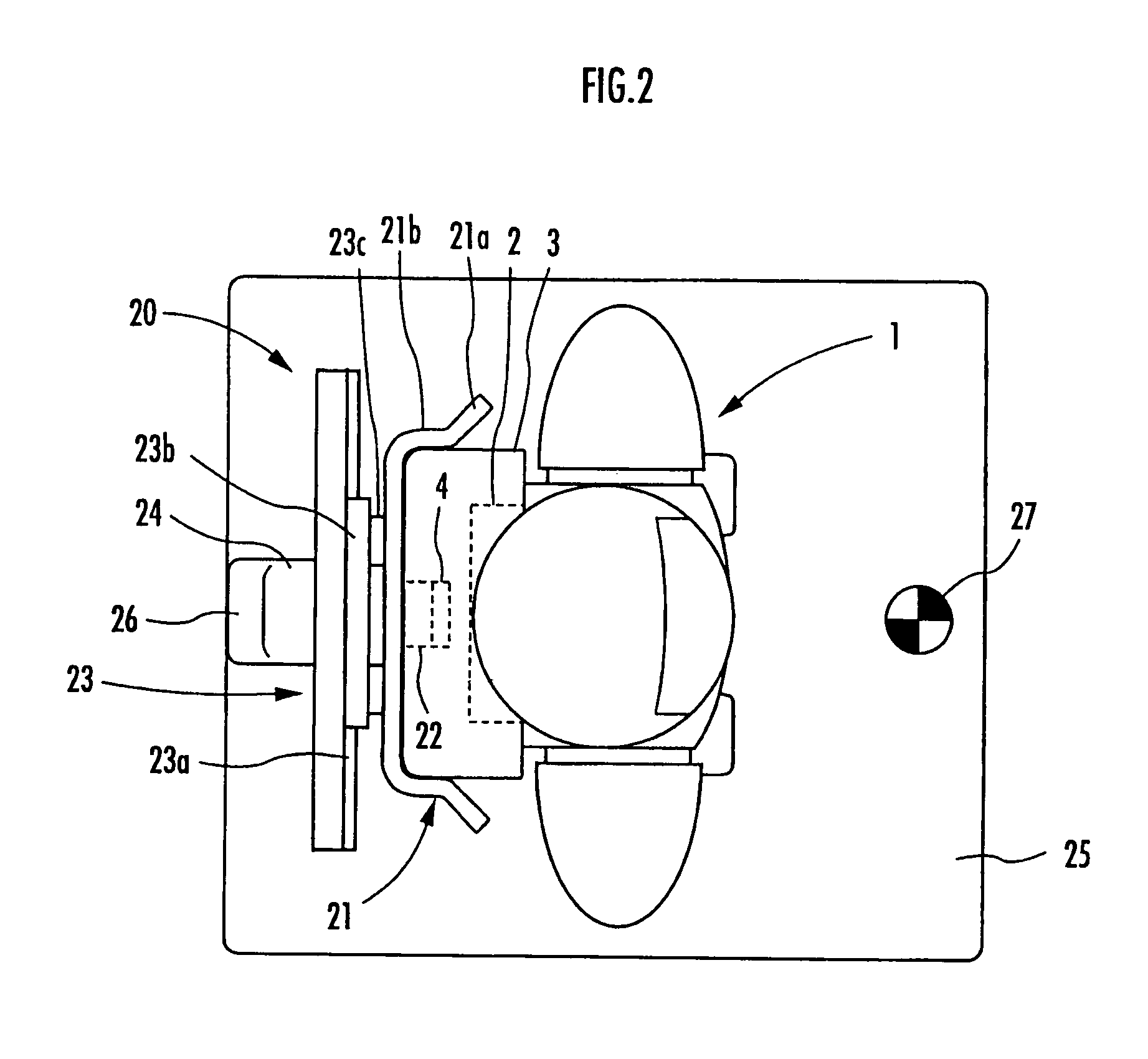
[0034]Now, a charging system according to an embodiment of the present invention will be described with reference to FIGS. 1 to 9. FIG. 1 is a diagram showing a robot that is being charged on a charging station of the charging system according to this embodiment. FIG. 2 is a plan view of the robot shown in FIG. 1 and some components arranged in the rear cover of the robot. FIG. 3(a) is a cross-sectional view of a power supplying connector and a power receiving connector, and FIG. 3(b) is a cross-sectional view taken along the line b-b in FIG. 3(a). FIG. 4 is a circuit diagram of the charging system according to this embodiment. FIG. 5 is a flowchart illustrating a charging operation of the robot. FIGS. 6(a) to 6(d) are diagrams for illustrating the charging operation of the robot. FIGS. 7(a) and 7(b) are diagrams for illustrating a connecting operation in the case where the robot and the charging station are misaligned with each other. FIGS. 8(a) to 8(d) are diagrams for illustratin...


PUM


Abstract

A charging system for a legged mobile robot that facilitates positioning of a robot to be charged and does not put a load on the robot is provided. The charging system includes a battery 2, a power receiving connector 4 and a movable shutter member 5 capable of being opened and closed on a rear cover 3, which are provided on a robot 1, and a holder 21, a power supplying connector 22, a slide mechanism 23, a base plate 25, a charging power supply 26 and the like, which are provided on a charging station 20. The robot 1 performs a predetermined positioning on the base plate 25 and then moves the center of gravity rearward to connect the power receiving connector 4 to the power supplying connector 22. In this step, when the rear cover 3 of the robot 1 is guided by a first guide section 21a of the holder 21, the slide mechanism 23 allows the holder 21 to move horizontally. Thus, even if the robot 1 and the charging station 20 are slightly misaligned with each other, the robot 1 can be easily positioned correctly.

Description

BACKGROUND OF THE INVENTION[0001]1. Field of the Invention[0002]The present invention relates to a system for charging a battery of a legged mobile robot.[0003]2. Description of the Related Art[0004]For example, Japanese Patent Laid-Open No. 2001-179663 discloses a system for charging a battery of a legged mobile robot configured as described below. A power receiving connector used for charging an internal battery is provided near the hip part of the robot, and a power receiving terminal is exposed on the surface of the power receiving connector. On the other hand, a charging station for charging the robot has a power supplying connector, and a power supplying terminals is exposed on the surface of the power supplying connector. The robot moves closer to the charging station and connects the power receiving connector to the power supplying connector. As a result, the power receiving terminal and the power supplying terminal are connected to each other, and the robot is charged.[0005...

Claims


Application Information

Patent Timeline
Patent Type & Authority Patents(United States)
IPC IPC(8): H01J7/00A63H30/00
CPCB25J19/005B60L11/1833H02J7/0042Y02T90/121Y02T90/125Y02T90/12Y02T90/14Y02T10/7005Y02T10/7072H01R13/2421H01R13/6315G05D1/0225G05D2201/0217B60L53/36Y02T10/70
Inventor KANEKO, SATOSHIOKAZAKI, KOJIMAKINO, HIROYUKINAKAYAMA, TAKASHIMUROMACHI, MASAAKI
Owner HONDA MOTOR CO LTD
Why Eureka
Try Eureka